AirGradient PRO PCB Update Review

I got burned by the USB-C port not doing data just a few days ago when I thought I had killed my board, but finally plugged in with the Micro-USB on the D1 and got it running.

If you are doing away with the D1 Shield pins, is there still a recommended way of adding a battery shield to the D1 itself or will it be too tight of a fit? I haven’t added one yet, but was thinking about it.

We will still keep the breakouts for G and 5V/VIN so you should be able to connect a charge controller.

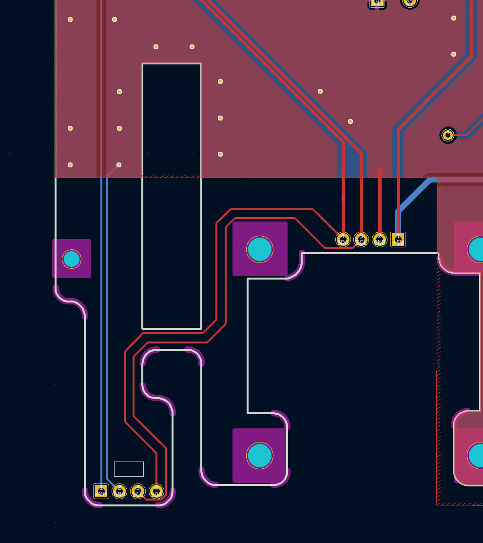
@Achim_AirGradient - The display that was supplied with my PRO kit failed in a matter of a few weeks. I tried to find a replacement on Amazon USA and 99% of my options had 3V3 and GND pins inverted. The only display that I found that had the 3v3/GND/SCL/SDA pinout was 3x more expensive (>$15) than all my other options and isn’t positioned perfectly (probably about 1mm to high up).

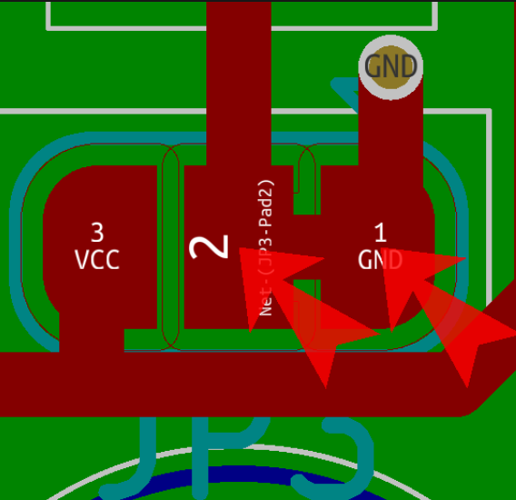
Could you kindly consider adding solder pads to allow inverting polarity? While I don’t like cutting traces, you could have the traces default to your preferred pinout and allow users to invert polarity by cutting the bridges and making new ones by soldering? I prefer 0 ohm resistors as I find it to be cleaner.

Found this on the web that shows what I mean:

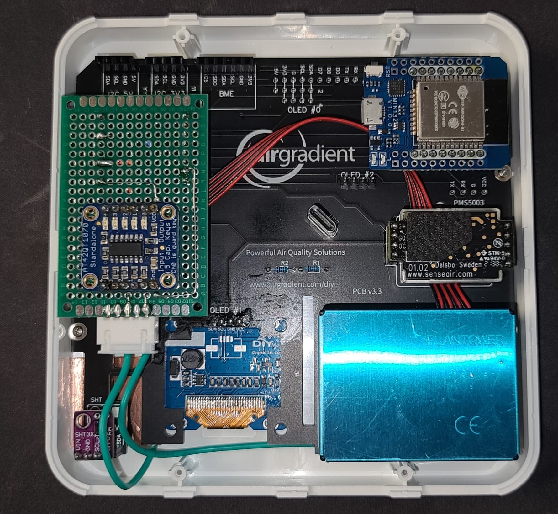
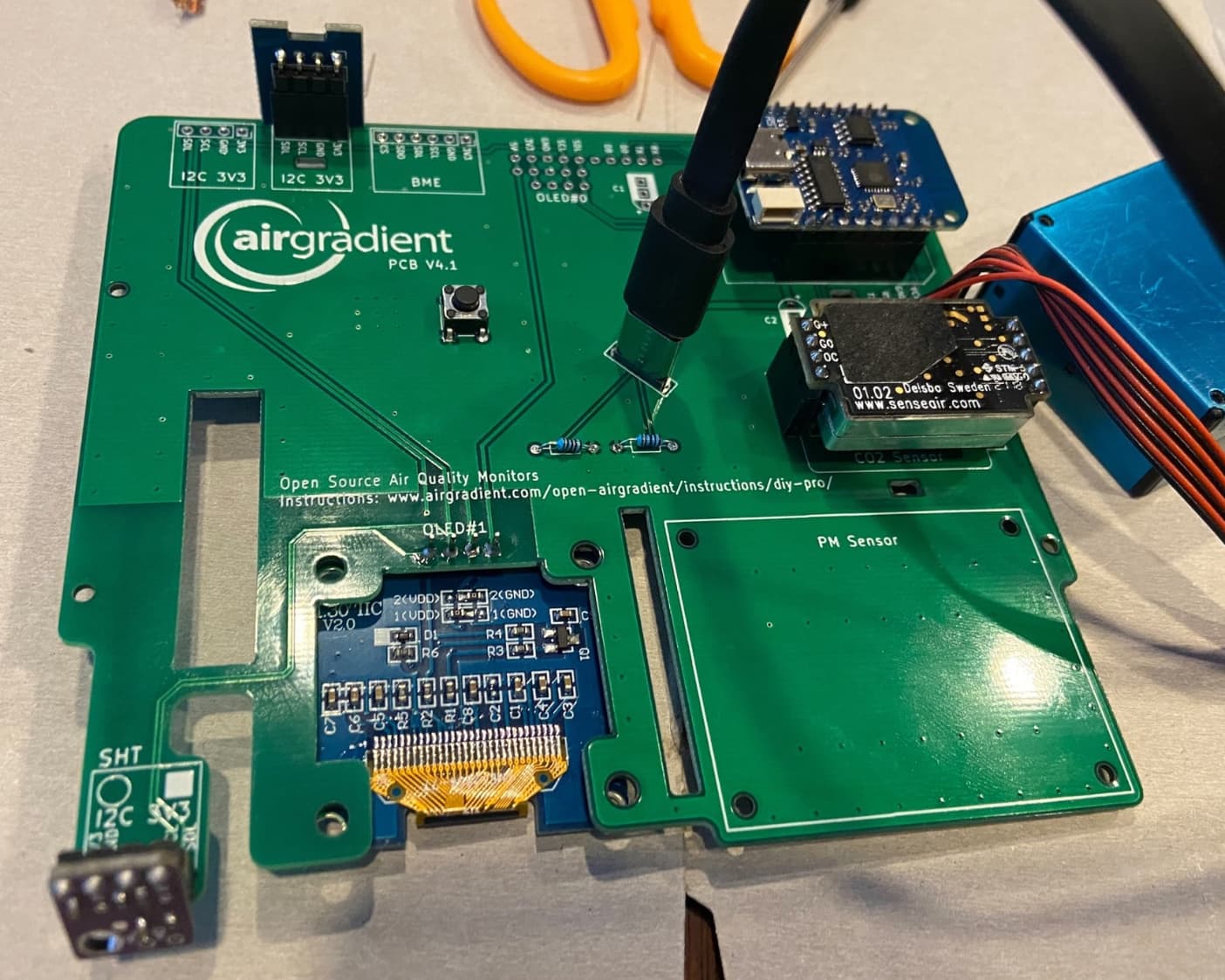
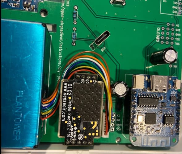
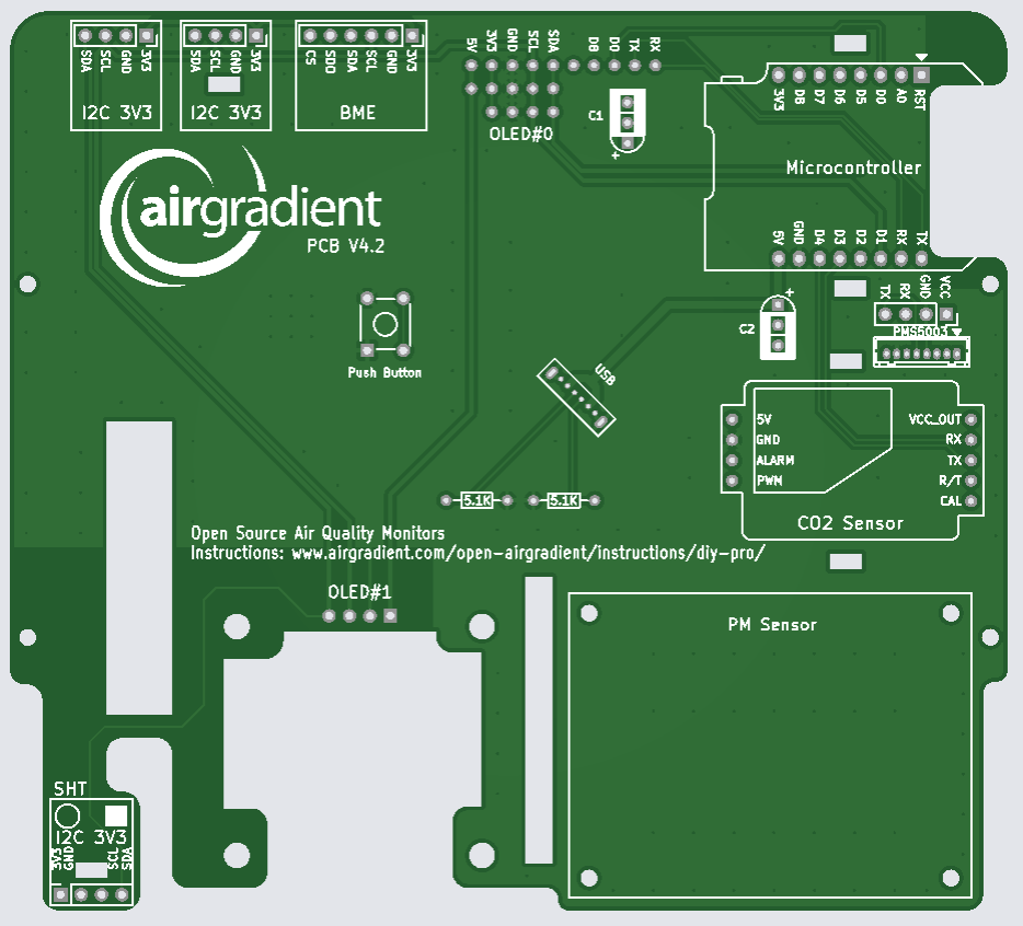
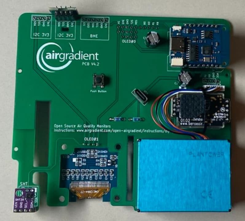
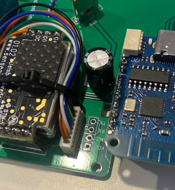
Also, I put an ESP32 in mine but the bottom left edge of the board interferes with the plastic molding. If the board were moved as much as possible to the right, it would allow more options (in the picture below I filed the board to make it fit… no traces harmed). It would also be great if there were solder holes, or the pins were routed to the shield location to enable adding additional hardware. I added touch sensors that work through the plastic case (green wires go to copper tape) to control the display which now defaults to off. I was limited to 2 GPIO if I tried to source them from the shield header even though my ESP32 mini has lots more.

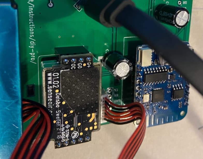
Excuse my crude breadboarding :slight_smile:

Our main focus with the redesign at the moment is to increase the stability of the board and reduce complexity so at this point in time we would like to focus on the changes discussed above.

Having said that, regarding your issues:

  1. OLED display pin sequence. Feel free to contact us and we can send you a replacement. Additionally these modules are available on AliExpress, e.g. here: https://www.aliexpress.com/item/32787898780.html

  2. Using an ESP32: You can use some of the newer ESP32 modules that have exactly the same size like the D1 ESP8266 module, e.g. : https://www.wemos.cc/en/latest/c3/c3_mini.html or S2 mini — WEMOS documentation

We do plan a major redesign of the board in the coming months, especially for the pre-soldered version and moving to an ESP32-C3. Main objective is to reduce the dependency on the D1 MCU modules that have caused a variety of issues in the past. The C3 has more I/Os which will then be broken out and accessible for custom developments.

1 Like

@Achim_AirGradient The OLED display you pointed me to has an estimated delivery of 2 months. Amazon USA is packed with a large number of displays that fit BUT the pinout has the power supply inverted. It leads to believe that the pinout you are using is the least popular one. It would be of great help to be able to switch polarity on the display even if using the cut trace and solder ball method which I assume does not add cost to the PCB. Please consider it. Inability to get spare parts in reasonable time or cost is a major drawback to an otherwise great design!

As for the S2 Mini, I tried one but could not get the UART to work. I use ESPHome and am not sure the S2 Mini is fully supported yet or there is some other issue. It is sometimes hard to figure out how to declare the board so that ESPHome knows how to use it… maybe that was my issue even though I use that board in other projects without issues. The one I ended up using is too large but with a couple modifications I got it to fit and most importantly, it worked perfectly immediately.

The shield header removal makes sense given there are very few usable pins (2 GPIO on PCB v3.3 in my case) but I hope you will add it back when you implement the ESP32 with more GPIO (please the 4 row pin version with more IO!) as it makes it much easier to add custom circuitry as I did (see image above).

I understand that the current focus is to increase stability, Achim, we hear you! :slight_smile:
I will stay say it, for future reference: the question about the pinouts for shields could be easily solved if the case had a little more space above the D1 (or C3 in the future). Any shield could then go piggyback on top of the D1/C3.

You can select faster shipping options in AliExpress. By default it shows the slowest and cheapest. Click on the shipping options and you can see faster ones.

We will also experiement with the C3 or S2 board as a D1 replacement and I will inform if we get it running.

The new design is already submitted for production but I made a note of better placement for the MCU to allow shields on top in one of the next updates.

We are currently making a sample production with a new version that incorporates the following changes:

  • ground plane
  • improved tracing
  • removed D1 shield
  • added capacitors (optional) on 3v3 and 5v
  • moved JST plug closer to MCU
  • button pulls to ground
  • OLED display is on 5v

Many thanks for the feedback, especially @ken830 and @l4ur for reviewing the schematics.

I should receive the new PCB next week for testing and will then give an update.

Could you send updated KiCad files for review?

Here are the new files: https://drive.google.com/file/d/1z6g0-oY6amFZzEOuNfQ8zrduPmo9SX5o/view?usp=share_link
Many thanks for reviewing.

Overall pretty good improvements considering your stated goals for this revision. Removing the shield and moving the PMS connector really eased the layout and made everything nicer.

I can see one small area of improvement. The SDA trace doesn’t need this extra transition to bottom layer if you just route SCL on the other side of it:

Like this:

Something to think about when you get an opportunity for the next batch if you’re already in fab with this version.

Got PCB version 4.1. yesterday and everything seems to work:

The PMS cable length is not ideal:

So we will probably switch to a smaller one with the kit.

image

I will post updated PCB files once we have these small changes done.

1 Like

Yay!

It’s looking great! Getting the OLED off the 3.3V rail is a big deal!

I just ordered the new PCB. Main improvements is the cutout around the WiFi antenna and some minor tracing and label improvements.

1 Like

@Achim_AirGradient - when would you anticipate the pcb v4.x selling? I’m looking to purchase a unit and am considering if I should wait or not.:upside_down_face:

By the way, reading the collaboration on this thread is exciting. Thanks to everyone that’s contributing!

1 Like

I expect a test board for v4.2 next week. Then if that works well, we will order higher quantities and put them into the shop but we also need to sell off the old boards first.

I think there is no fundamental issue with the previous PCB versions and most problems that people have @ken830 narrowed down on the software serial library. I have many DIY kits with the previous PCB versions running stable. Anyway, I will keep on putting updates in here about the test results and availability.

1 Like

Have you considered adding a cutout under the D1? This comment suggested it would improve wifi signal strength. There might be something to that. The current signal strength seems to be good enough in my setup, but my wifi access point does say the my kitchen AirGradient device’s “experience” is lower than anything else in the house (at 72%).

edit: oh, I just noticed in this comment you did exactly that. Neat!

Understood - thanks for the context!

I received the new version and everything looks good and seems to work:

Here you can see the PCB cutout under the D1 mini antenna:

I will test a few days more and then if all is well publish the new instructions including files.

3 Likes