@LW14 please check that the plug is fully pressed into the PM sensor. It appears on the photo that it is not fully inserted.
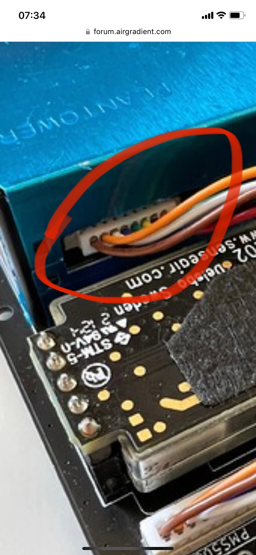
I made sure it is inserted, then tried again. It is still showing a PM of -1. Are my soldering location and cable positioning correct? (are there any other problems?)
So far all looks good (correct cable). Can you show the opposite side of PCB so that we can see the solder points of the JST plug:
Do you hear the fan spinning on the PM sensor?
(it is very faint so you need to hold it directly at your ear).
If the soldering is the only thing that could be wrong besides the plug not being pushed in all the way, then that’s fine. Also I don’t hear the fan spinning, could it be the power not reaching the solder points with the JST connector?
No it looks ok. The colors are different on some of the cables but the jst plug is soldered correct orientation.
For seating the cable on the sensor, I had to use a thin tool to push the connector fully in. I couldn’t get it with just my fingers.
yeah, i did that too with a small screwdriver.
can you take a picture of your board, specifically the PM sensor area if it works? that would help a lot, thanks.
Can you test the cable and also check the connectors on the PCB and the PM sensor if one of the metal pins is bend?
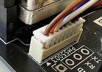
@Achim_AirGradient for me the PMS is detected when the JST is rotate 180 degrees according to the pic above. Fans don’t spin in t he orientation above. This is on the v4.2 board.
Mind you that I didn’t buy the kits, I have a regular black and red cable. The language of the cross-over cable is a bit confusing. It is unclear what this refers to form the text alone. A picture may help. If the wiring inside the cable reverses the plugs then don’t regard my comment.
Finally got around to opening up the case. Maybe an improvement for future versions is a tool-less case?
Here you go.
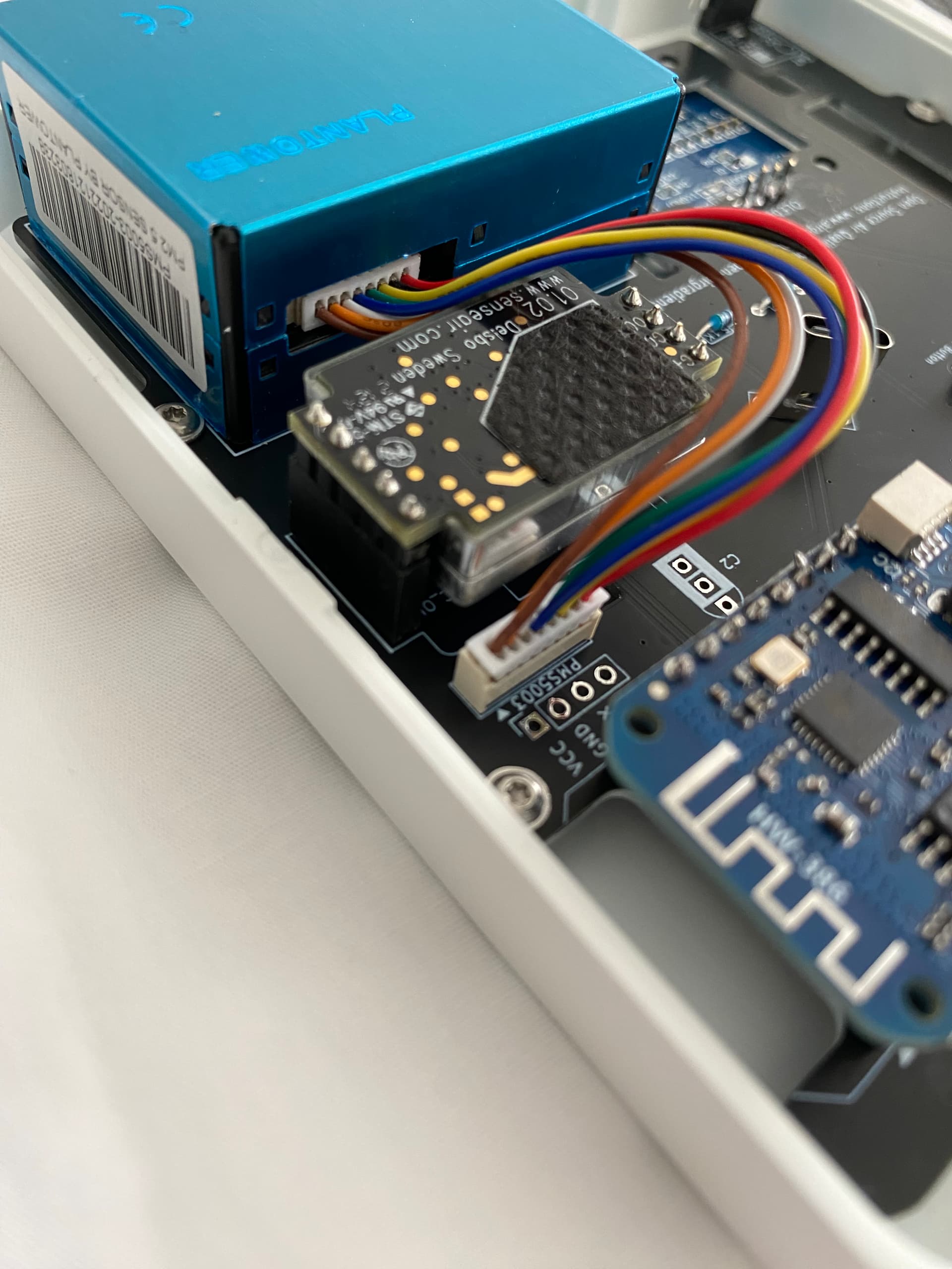


Thank you for the reference @vlotty! I originally had my connector like yours, but none of my PMS sensors are detected that way. I soldered the connector rotated in the same spot, and it immediately was connected. Cable looks linear to me so I’m not sure what to conclude here other that perhaps my PMS sensors have a swapped connector(!?).
Can you confirm @lw14 that the orange wire of the PMS connects to ground? You can check this by probing the 2nd pin with any metal part of the case on the PMS.
EDIT [new users can edit more than 3 times on a post?] @LW14 did you end up flipping the connector? Im still a bit baffled by the orientation tbh.
thank you for the images! that really helps
I fixed it. It turns out i needed more solder on the second pin and some changes in the orientation. Thank you all for helping!
This is how you can easily identify cross over cables:
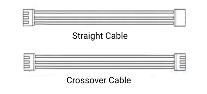
All our kits EXCEPT the basic kit use cross over cables.
It looks like you got a straight cable. Did you purchase the cable yourself or was it part of the kit we sell (which shouldn’t happen)?

I think I read over this! This explains why my 180 degrees connector works too. All is clear thanks.