I’m using the unsoldered version of the pro kit. I found the instructions online not clear of how I should install the PM sensor cable onto the PCB 4.2. (I’m a beginner). Please show me how to do this. Thanks!
One end of the cable has two parts, you solder the female connector part to the PCB, and can plug in the other part after it’s on. It’s very small so you might need something thin to help you separate.
it says in the instructions a cross-over cable is required for a PBC 4.2, what does that mean and should I just ignore it and do what you said?
I’m not seeing mention of a cross-over cable.
Do you mean this section?
Connecting The PMS5003 (PMS Sensor) Cable
The PMS Sensor is connected with a cable to the PCB. There are two ways to connect it. If you can solder the small JST connector, then solder it on the board:
If you’re able to solder the connector part from the cable, I would do that. The next section is only if you prefer to solder the cable directly to the board.
Connecting The PMS5003 (PMS Sensor) Cable
The PMS Sensor is connected with a cable to the PCB.
Please note that from PCB Version 4.2 a smaller cross-over cable is required. The red-black cable often coming with the PMS sensor is not a cross-over cable and it will not work with the JST plug. In case you have the wrong cable, you can splice it and solder it into the through holes provided (see below).
There are two ways to connect it. If you can solder the small JST connector, then solder it on the board:
I think my cable matches what was in the photo, which I assumed to be the newer cable, and I just soldered the JST connector as directed.
Facing the same problem. I soldered the female connector to the board. I have two sensors here but both of them don’t work. The PCB implies that the “tab” side (the side where the female connector has holes) is facing in the direction of the PMS sensor. Using that method, however, the sensors I have are not registered. The cross-over cable terminology is also throwing me off. The vcc pin should be facing the right when looking at the PMS sensor on the back. This would imply that I soldered the connector correctly.
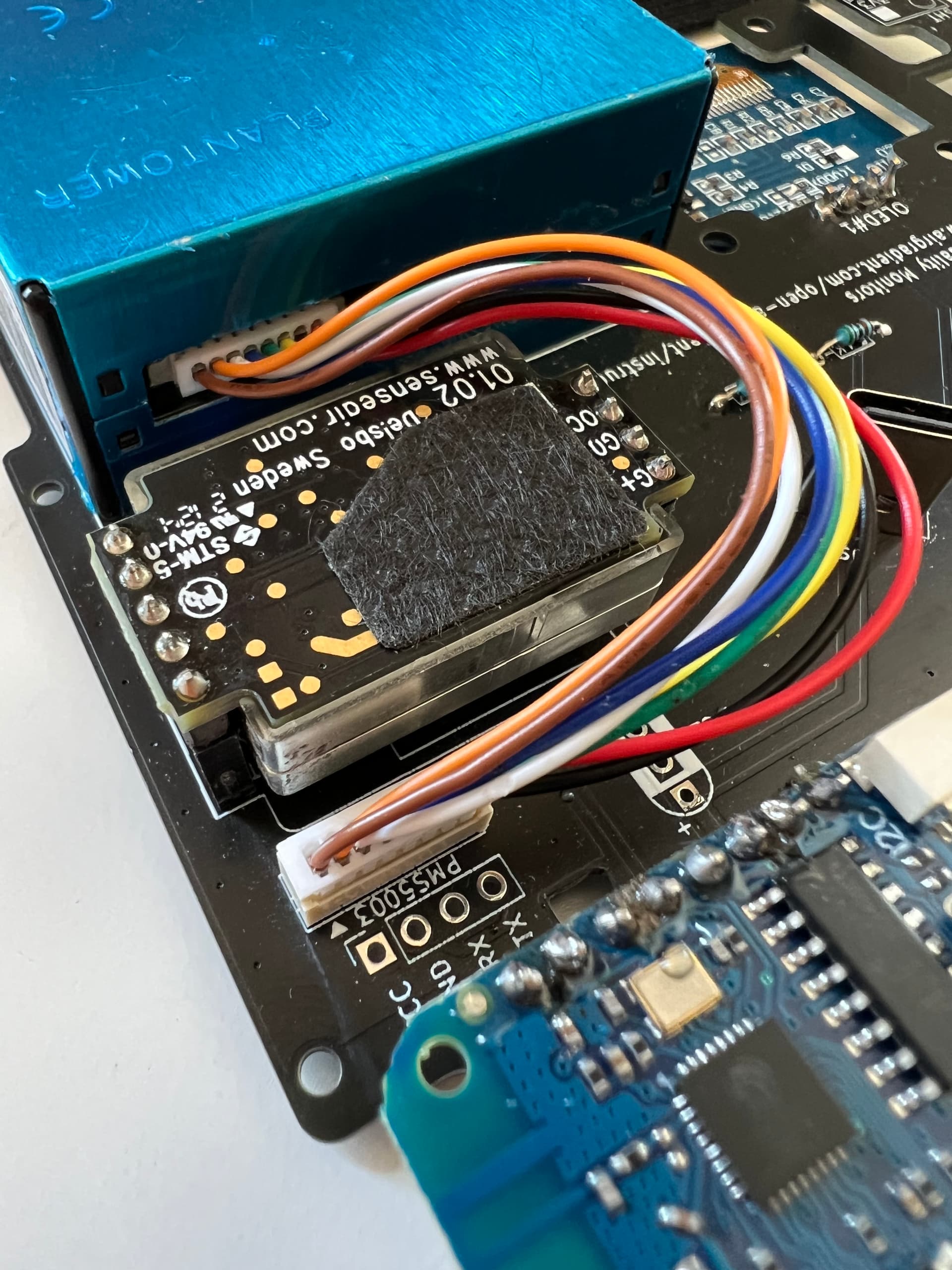
Can someone send an image of a working PM Sensor on a PCB 4.2? Thanks. Here’s mine, and it shows a PM of -1:
Thanks!
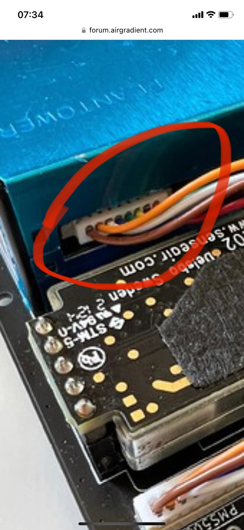
This might sound silly, but I had this problem at first too and discovered that the cable wasn’t fully seated all the way on the sensor end.
Do you have a picture of a working one?
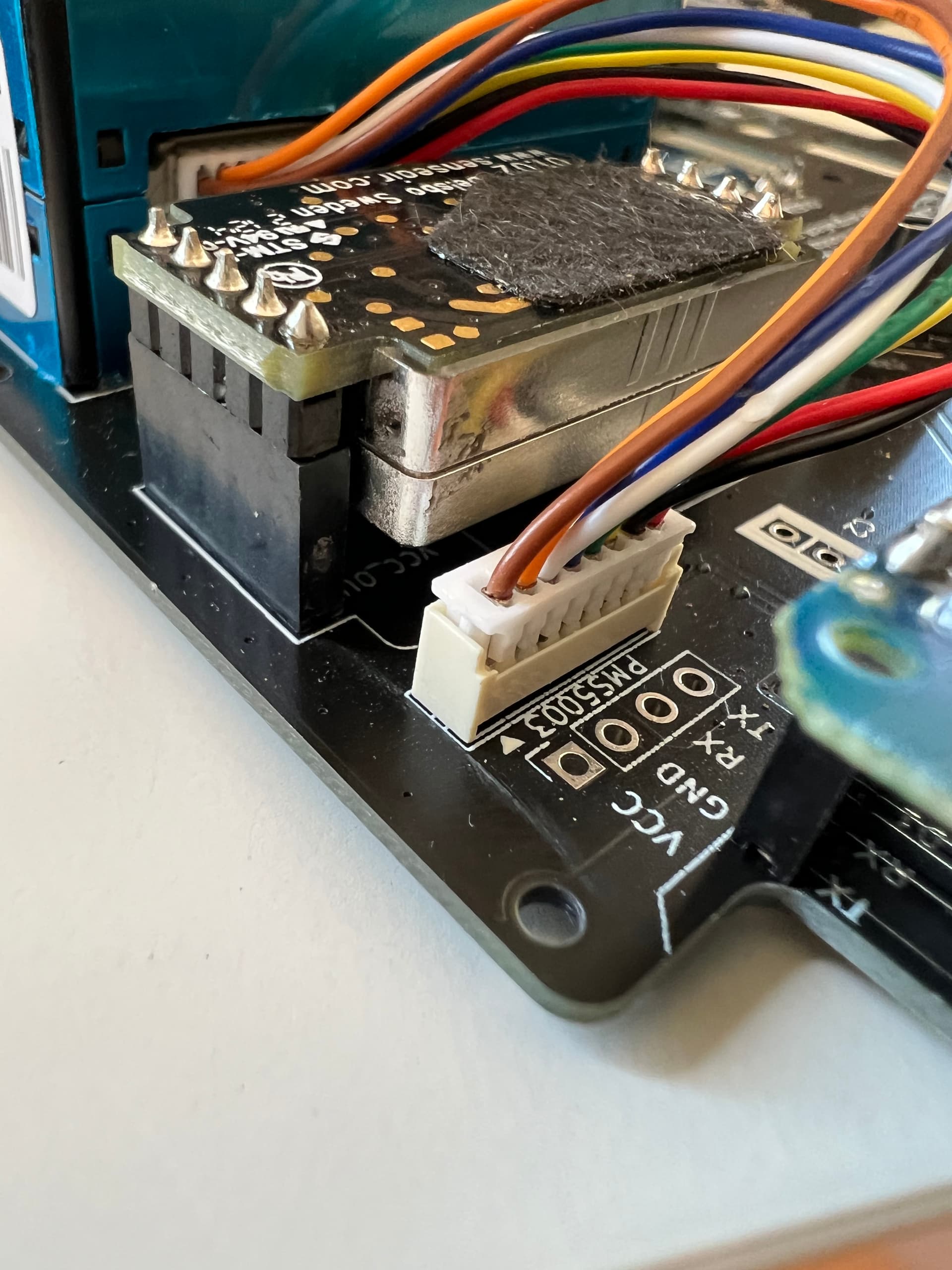
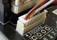
@LW14 please check that the plug is fully pressed into the PM sensor. It appears on the photo that it is not fully inserted.
I made sure it is inserted, then tried again. It is still showing a PM of -1. Are my soldering location and cable positioning correct? (are there any other problems?)
So far all looks good (correct cable). Can you show the opposite side of PCB so that we can see the solder points of the JST plug:
Do you hear the fan spinning on the PM sensor?
(it is very faint so you need to hold it directly at your ear).
If the soldering is the only thing that could be wrong besides the plug not being pushed in all the way, then that’s fine. Also I don’t hear the fan spinning, could it be the power not reaching the solder points with the JST connector?
No it looks ok. The colors are different on some of the cables but the jst plug is soldered correct orientation.
For seating the cable on the sensor, I had to use a thin tool to push the connector fully in. I couldn’t get it with just my fingers.
yeah, i did that too with a small screwdriver.
can you take a picture of your board, specifically the PM sensor area if it works? that would help a lot, thanks.
Can you test the cable and also check the connectors on the PCB and the PM sensor if one of the metal pins is bend?