New AirGradient DIY Kit Version 3 Feedback and Discussion

I would like to share with you that we are working on an updated DIY kit.

The two main downsides of the current DIY kit are that people need to print their own enclosure and that due to the small size, the temperature sensor gets too hot from surrounding components and can be 1.5-2 degrees celcius above ambient temperature.

So we are currently designing an additional DIY kit that addresses these issues.

Enclosure
For our professional AirGradient ONE sensor we designed our own plastic injection-molded enclosure that looks great, has enough space for sensors add-ons, cable management (cable from top or bottom or directly from behind), and is optimized for airflow and accurate measurements.

The enclosure looks like this:
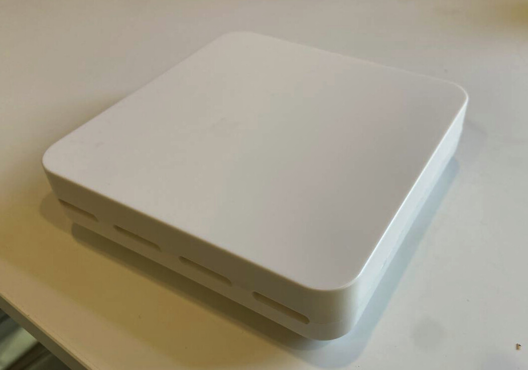
Backside

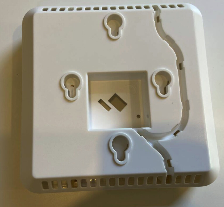
So we thought, why not use this enclosure for our next generation DIY kit?

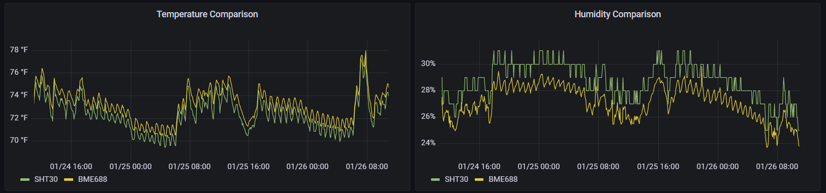
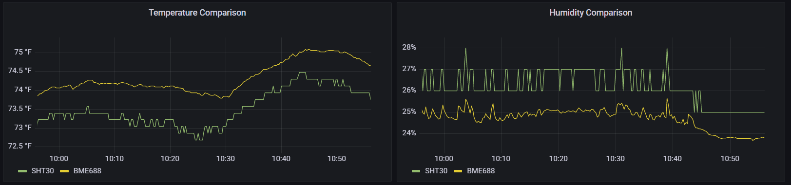
Redesigned PCB with accurate Temperature Measurement
The bigger enclosures give us the possibility to isolate the temperature sensor inside the enclosure and make use of the airflow characteristics that we specifically designed this enclosure for. As a result, the temperature measurements will be very close to ambient temperature (probably in the range of 0.2-0.4C to ambient).

The larger PCB also allows for more extensibility, e.g. a separate D1 shield area where e.g. a batterie shield can be plugged in and enough space for additional sensors.

Here is a picture of the current prototype DIY v2 PCB:
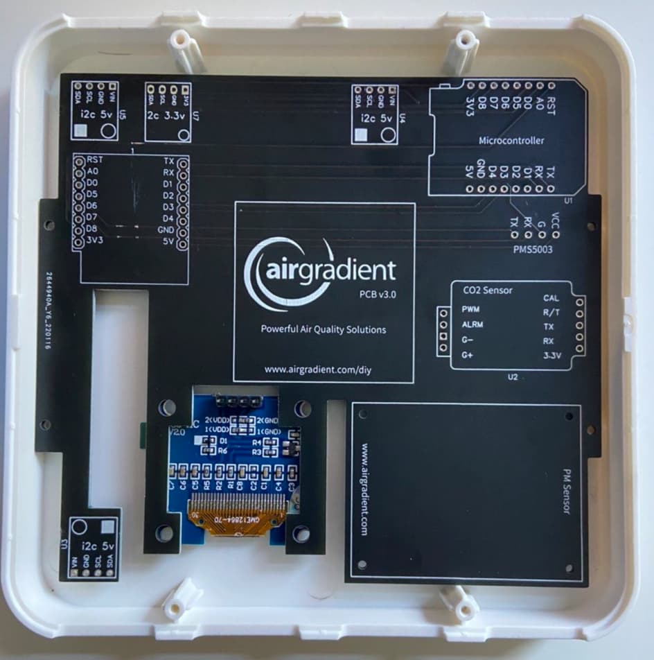
and with components

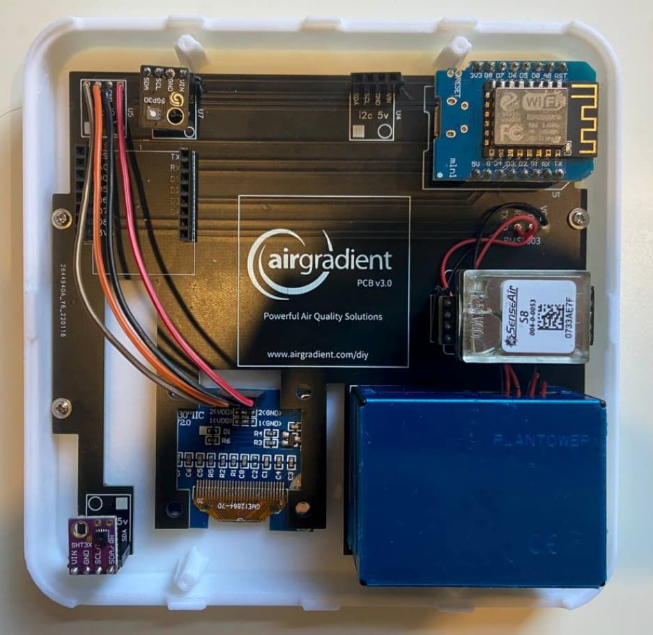
We are planning to add a lot more empty pins on the board to allow people adding their own extensions.
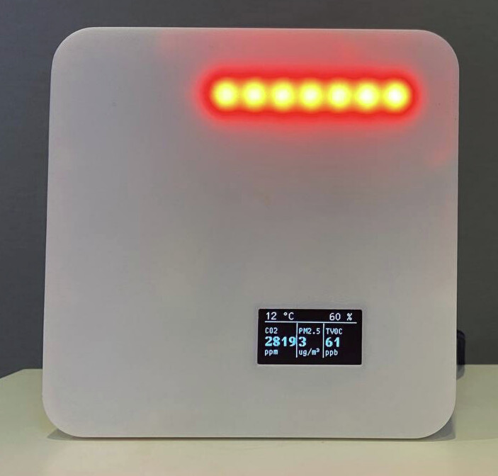
Larger OLED Display

We would also go for a slightly larger 1.3 inch OLED display that would allow to display all air quality parameters at the same time:

image

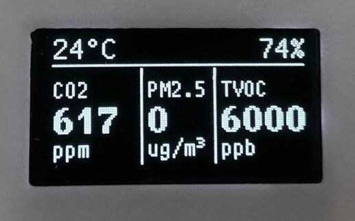
The plastic injected enclosure would then have a cutout to fit in that display.

Summary
Enhanced AirGradient DIY Kit Version 2 comes with a professional, nice-looking enclosure and is more accurate due to its better thermal characteristics. Probably still using the same sensor components with a slightly larger display. Besides the enclosure, we might also add cable, power plug, and a TVOC sensor module to this new kit. We try and keep it compatible with our Open Source AirGradient Arduino library.

Please let me know your thoughts and feedback on this!

9 Likes

Hey @Achim_AirGradient,

great news! Let me share my thoughts.

What I like:

  • Larger OLED display
  • Modularity of the new PCB
  • Look of the enclosure

Improvement suggestions:

  • I would vote against putting a USB cable and power plug into the kit. Power plugs differ around the world and people might have very different requirements for the length and looks of the cable. Plus, both cable and power plug should be easy to source anywhere.
  • Have you considered moving from an ESP8266 to an ESP32? I do not see direct advantages for the kit itself but the ESP32 comes with Bluetooth, which could be helpful for monitoring other devices if someone is not already running a base station for Bluetooth sensors. For me, this would eventually be a price decision. Could you share how large the price difference between an ESP8266 and an ESP32 is at your supplier?
  • I think the U7 element on the PCB might have a typo because it reads ā€œ2cā€ instead of ā€œi2cā€. In addition, I would suggest to rename this to ā€œi2c 3v3ā€ to be consistent with the pin name on the MCU.
  • Have you considered including a placeholder for sensors with other pin layouts? Iā€™m asking because I stumbled across the Bosch sensor palette such as the BME680 the other day. That sensor has 6 pins on the breakout boards I discovered so far (e.g., Amazon). I donā€™t know how often this pin layout occurs across sensors but maybe it is worth considering other pin layouts in general.

Questions:

  • What is the functionality of the PCB cut-out between the display and the temp sensor? Is it just to save material? Same questions applies to the cut-out right of the display.
  • Could you share which OLED display you plan on using? A few others and me are using ESPHome for the software side so it would be great to check upfront if the display is supported or easy to implement as a new component.
2 Likes

Many thank for your feedback.

We did extensive testing on our professional sensor and found out that the PCB transmits heat much stronger than air. The PMS sensor with its laser and fan is a heat source. So to get an accurate temperature reading the air gaps are required.

OLED display is standard 1.3 for example the ones you get on AliExpress.

Yes we are also considering the ESP32 and looking for ways to make the PCB compatible also for the Wemos Mini ESP32 version.
We do like the ESP8266 as it has been proven extremely reliable (more so than the ESP32) and thus think it is a good idea to continue using it.
However, the ESP8266 also has limitations, e.g. no additional hw serial pins etc.

We can consider placeholders for other sensors. Please post what sensors you normally use.

1 Like

As for other sensors, I only started exploring the microelectronics and air quality worlds when I stumbled upon the DIY kit so I do not have any other sensors as of now. However, I was at least considering to look at some of the Bosch BME sensors. They seem more expensive but maybe they are of interest to some people around here. Plus at least for Europe they seem easy to source.

I like what I see, as Ibhm has covered in detail.

One idea: have you considered mounting the PM2.5 sensor entirely off-board, i.e. on the case rather than on the PCB. Since itā€™s wired in with cabling anyway, it doesnā€™t need to be on-PCB. Of course that then changes the kit to almost require the case. Or maybe two variants, one with this PCB, case sold separately, and one with the smaller/different PCB but case included? It would muddy the ā€œproduct lineā€, I guess.

Also, can you include a zoomed-out pic where we can see where the display would be visible on the complete assembly? Itā€™s kinda unclear with the current pictures.

I strongly agree with Ibhm regarding power plug and cable. Maybe a USB cable, but I wouldnā€™t include the wall wart/power plug for the reasons mentioned.

Here is a picture of the front:

It includes an optional LED Strip that shines through the enclosure and could be added relatively easily.

@klausman What would be the advantage to not mount the PMS sensor on the PCB? Would you still put the PMS inside the enclosure? To be honest I do not really understand the reasoning behind your comment.

2 Likes

What would be the advantage to not mount the PMS sensor on the PCB? Would you still put the PMS inside the enclosure? To be honest I do not really understand the reasoning behind your comment.

The idea being that if the PCB is a (relatively) good heat conductor, having no contact with it at all would be even better than spacing things out. Not sure if the case itself would carry heat just as well as the PCB does.

I like the new kit except it looks like the breakouts from the original board are gone. I did notice the additional I2Cs breakouts on the upper left.

For my builds I have been using a SGP30, and for the specific sensor Iā€™m using (Adafruit STEMMA SGP30), Iā€™ve actually had to use jumpers because itā€™s not pin compatible with the board. I used this because thereā€™s a regulator on board and the data sheet for the SGP sensor says it needs1.8V. Not all of the pin compatible breakouts have this regulator/shifter. (I burned the original one I sourced.)

With regards to the mounting location of the SHT sensor, I saw the results from forum user @ttielemans , and intended on removing the SHT sensor entirely. Iā€™ll be replacing the PMS5003 with the PMS5003T.

I like the idea of optionally including an enclosure, if that is what you are suggesting. I used a 3rd party 3d printer and would rather have contributed the Ā£ to you. Luckily I live where there are plenty of choices but many people would have less or no choice.

Looks good, one other item that I think needs addressing are power requirements. Iā€™ve seen many issues raised on the message board about inconsistent or irregular readings, and alot of this stems from insufficient power being fed into the unit. I personally experienced this until eventually upgrading to a higher quality 5v power supply. I would recommend making this an optional add on.

As someone who does not have a 3d printer, I would be someone who would be interested in one of the new enclosures.

1 Like

Any chance the LED strip can be populated with square or rectangular LEDs, so the bar-style display can appear more ā€˜fluidā€™ (or is that entirely up to the constructor)?

Adding my vote against bundling USB cables or power supplies with the kit, but of course theyā€™d be welcome as an optional add-on.

Does the new PCB address the issue with the AG using IO pin D4 and flashing the on-board LED intermittently?

- G.

As someone that just built one of the current DIY kits I have a few comments.

I like the idea of a better case. I was unable to get a good print for the temperature sensor extension.
I like that the components will not need to be stacked.

I did like the breakout holes on the older board, but they didnā€™t have proper spacing, so the headers included in the kit could not be used.
I tried the SPG30, but had problems getting readings from it (as others have mentioned in the forum). I swapped it for a Bosch BME688 (adafruit module) which seems to work fine.

From the pictures, there donā€™t seem to be vents on the sides where the CO2 sensor goes. Cross air flow might be nice and not really impact the case look (maybe your engineering has shown it not necessary).
I would like the LED lights/bar to either be optional or software controlled so it can be turned off. Personally I think the OLED communicates enough without being distracting.

Looks good.

Good points with the breakout pins and proper spacing.

Our enclosure was designed to create a chimney air flow in order to get the most accurate readings at the bottom of the enclosure where the temperature sensor is located. We experienced with side vents but that did not bring any additional benefits.

We also looked at the BME680 but found it to substantially overstate the temperature. Did you compare your readings to a reference thermometer?

One other small bit of feedback, is it perhaps possible to design the board with onboard temp, humidity, and VOC? As in actually part of the main board instead of using modular sensors?

I know that means assembly then becomes just the Wemos, LCD, and PMS.

Iā€™m also aware that removes the ability to change the sensors easily, and may conflict with the idea of ā€œDIYā€, so perhaps a bit controversial, but if the sensors were positioned for accuracy perhaps people wouldnā€™t be interested in using different kinds of sensors if the readings from the onboard sensors ā€œjust work ā€œ

@brianFromNyc I used the PMS5003T on my build which also measures temperature and humudity. The PMS5003ST can measure temperature, humidity and VOC. The only ā€œissueā€ is the price. The cheapest I could find, was maore than double the price of the PMS5003. The PMS5003T is slightly more expensive but cheaper than the PMS5003+SHT31.

1 Like

I am running with both the SHT30 and the BME688. Here are some comparisons:
2 days

1 hour

I have not compared these values to a reference thermometer yet.
The BME688 values are using the ā€œcompensatedā€ temp and humidity values. I havenā€™t looked at the ā€œrawā€ output yet.

1 Like

Another question regarding the new enclosure just popped up in my head:
Do the (two horizontal) mounting holes of the new case by any chance have the same spacing as the current case? This would prevent me and others from having to drill new holes for a wall mount. I realize that this might not be a big deal for some people but since I currently live in a rented apartment with no clue about whatā€™s inside the walls, I try to keep my drilling activities minimal.

It looks like the BME is consistently higher than the SHT which is similar to our observation. It would be great to see the comparison to a reference thermometer if available.

it will have different spacing but the new enclosure should fit above European and US junction boxes and the spacing of the screws should just fit to these junction boxes.