New AirGradient DIY Kit Version 3 Feedback and Discussion

Here is a picture of the front:

It includes an optional LED Strip that shines through the enclosure and could be added relatively easily.

@klausman What would be the advantage to not mount the PMS sensor on the PCB? Would you still put the PMS inside the enclosure? To be honest I do not really understand the reasoning behind your comment.

2 Likes

What would be the advantage to not mount the PMS sensor on the PCB? Would you still put the PMS inside the enclosure? To be honest I do not really understand the reasoning behind your comment.

The idea being that if the PCB is a (relatively) good heat conductor, having no contact with it at all would be even better than spacing things out. Not sure if the case itself would carry heat just as well as the PCB does.

I like the new kit except it looks like the breakouts from the original board are gone. I did notice the additional I2Cs breakouts on the upper left.

For my builds I have been using a SGP30, and for the specific sensor I’m using (Adafruit STEMMA SGP30), I’ve actually had to use jumpers because it’s not pin compatible with the board. I used this because there’s a regulator on board and the data sheet for the SGP sensor says it needs1.8V. Not all of the pin compatible breakouts have this regulator/shifter. (I burned the original one I sourced.)

With regards to the mounting location of the SHT sensor, I saw the results from forum user @ttielemans , and intended on removing the SHT sensor entirely. I’ll be replacing the PMS5003 with the PMS5003T.

I like the idea of optionally including an enclosure, if that is what you are suggesting. I used a 3rd party 3d printer and would rather have contributed the £ to you. Luckily I live where there are plenty of choices but many people would have less or no choice.

Looks good, one other item that I think needs addressing are power requirements. I’ve seen many issues raised on the message board about inconsistent or irregular readings, and alot of this stems from insufficient power being fed into the unit. I personally experienced this until eventually upgrading to a higher quality 5v power supply. I would recommend making this an optional add on.

As someone who does not have a 3d printer, I would be someone who would be interested in one of the new enclosures.

1 Like

Any chance the LED strip can be populated with square or rectangular LEDs, so the bar-style display can appear more ‘fluid’ (or is that entirely up to the constructor)?

Adding my vote against bundling USB cables or power supplies with the kit, but of course they’d be welcome as an optional add-on.

Does the new PCB address the issue with the AG using IO pin D4 and flashing the on-board LED intermittently?

- G.

As someone that just built one of the current DIY kits I have a few comments.

I like the idea of a better case. I was unable to get a good print for the temperature sensor extension.
I like that the components will not need to be stacked.

I did like the breakout holes on the older board, but they didn’t have proper spacing, so the headers included in the kit could not be used.
I tried the SPG30, but had problems getting readings from it (as others have mentioned in the forum). I swapped it for a Bosch BME688 (adafruit module) which seems to work fine.

From the pictures, there don’t seem to be vents on the sides where the CO2 sensor goes. Cross air flow might be nice and not really impact the case look (maybe your engineering has shown it not necessary).
I would like the LED lights/bar to either be optional or software controlled so it can be turned off. Personally I think the OLED communicates enough without being distracting.

Looks good.

Good points with the breakout pins and proper spacing.

Our enclosure was designed to create a chimney air flow in order to get the most accurate readings at the bottom of the enclosure where the temperature sensor is located. We experienced with side vents but that did not bring any additional benefits.

We also looked at the BME680 but found it to substantially overstate the temperature. Did you compare your readings to a reference thermometer?

One other small bit of feedback, is it perhaps possible to design the board with onboard temp, humidity, and VOC? As in actually part of the main board instead of using modular sensors?

I know that means assembly then becomes just the Wemos, LCD, and PMS.

I’m also aware that removes the ability to change the sensors easily, and may conflict with the idea of “DIY”, so perhaps a bit controversial, but if the sensors were positioned for accuracy perhaps people wouldn’t be interested in using different kinds of sensors if the readings from the onboard sensors “just work “

@brianFromNyc I used the PMS5003T on my build which also measures temperature and humudity. The PMS5003ST can measure temperature, humidity and VOC. The only “issue” is the price. The cheapest I could find, was maore than double the price of the PMS5003. The PMS5003T is slightly more expensive but cheaper than the PMS5003+SHT31.

1 Like

I am running with both the SHT30 and the BME688. Here are some comparisons:
2 days

1 hour

I have not compared these values to a reference thermometer yet.
The BME688 values are using the “compensated” temp and humidity values. I haven’t looked at the “raw” output yet.

1 Like

Another question regarding the new enclosure just popped up in my head:
Do the (two horizontal) mounting holes of the new case by any chance have the same spacing as the current case? This would prevent me and others from having to drill new holes for a wall mount. I realize that this might not be a big deal for some people but since I currently live in a rented apartment with no clue about what’s inside the walls, I try to keep my drilling activities minimal.

It looks like the BME is consistently higher than the SHT which is similar to our observation. It would be great to see the comparison to a reference thermometer if available.

it will have different spacing but the new enclosure should fit above European and US junction boxes and the spacing of the screws should just fit to these junction boxes.

Mounting the SHT and TVOC sensors directly would probably not make much difference from soldering a module on the same spot. However it is something we look into in case we will offer a pre assembled kit.

I can’t speak for all users, but personally I use AirGradient so I can get data into Prometheus. The DIY portion for me is because it’s the cheapest way, and I have the skills for both programming the Arduino and soldering the kit.

If there was an affordable way to get accurate air quality data into Prometheus, for instance a preassembed Wemos or Lolin D1 with accurate sensors, I would use that instead. Bonus points if it functions as a Prometheus metrics endpoint without me having to flash it.

I like the look and the optional headers for other sensors. I’m on board!

Thank you for the valuable feedback.

I want to share with you an update on the DIY v2 design.

I incorporated the following:

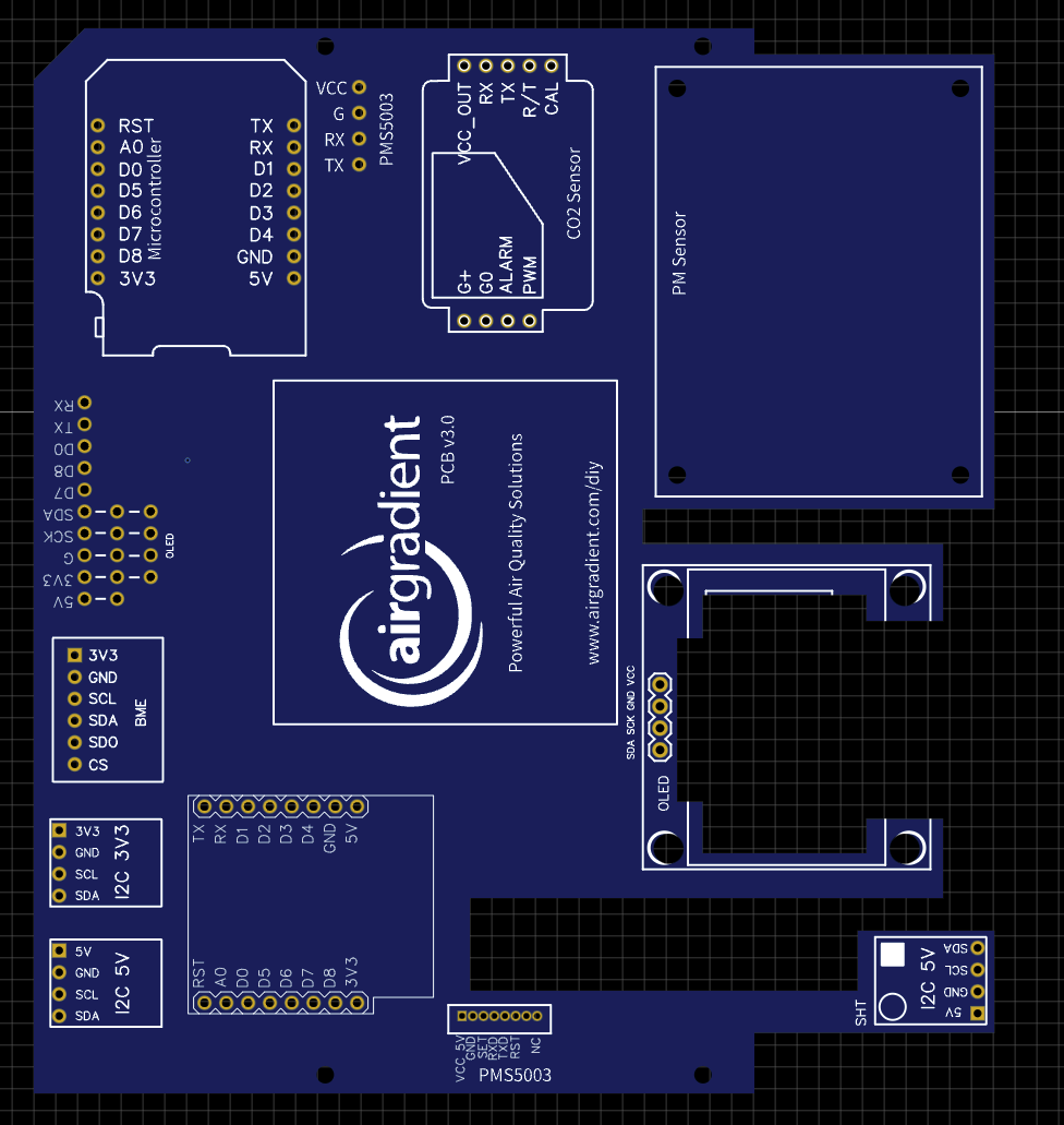
  • added the breakout pins (now compatible with 2.56mm pin headers)
  • added a Bosch BME sensor slot
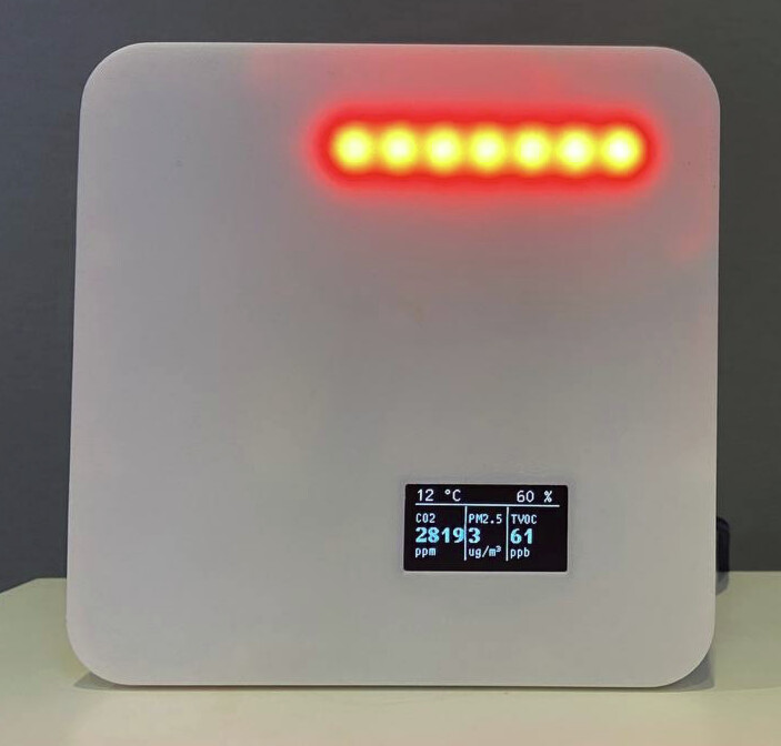
  • added a slot for the bigger OLED display either on the front or backside
  • added a 2nd PMS connector that fits the standard cable
  • improved the naming conventions
  • flipped the S8 sensor to have the air intake on the top (in line with the recommended mounting direction)

I experienced with the ESP32 mini but it is difficult to get it placed inside the enclosure also due to the cable coming out of it that needs space. So at the moment, I believe it’s better to stick with the ESP8266.

Here is the current layout.

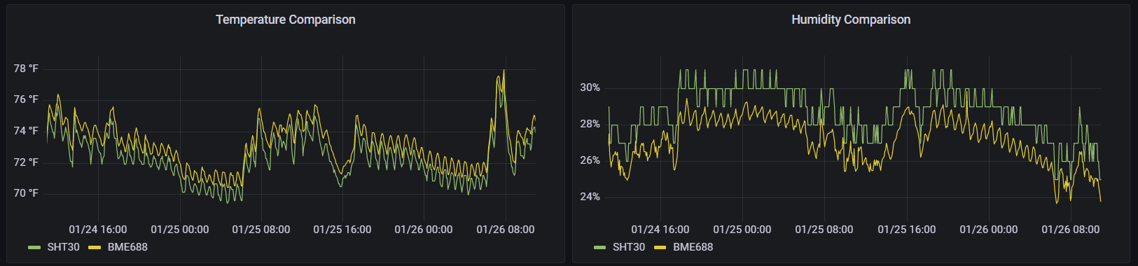
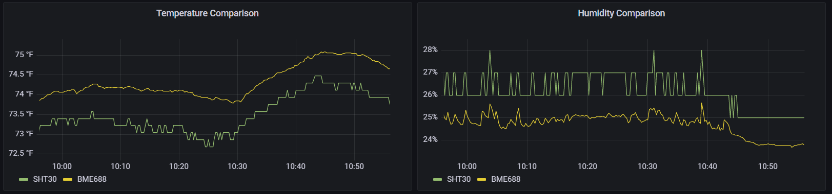
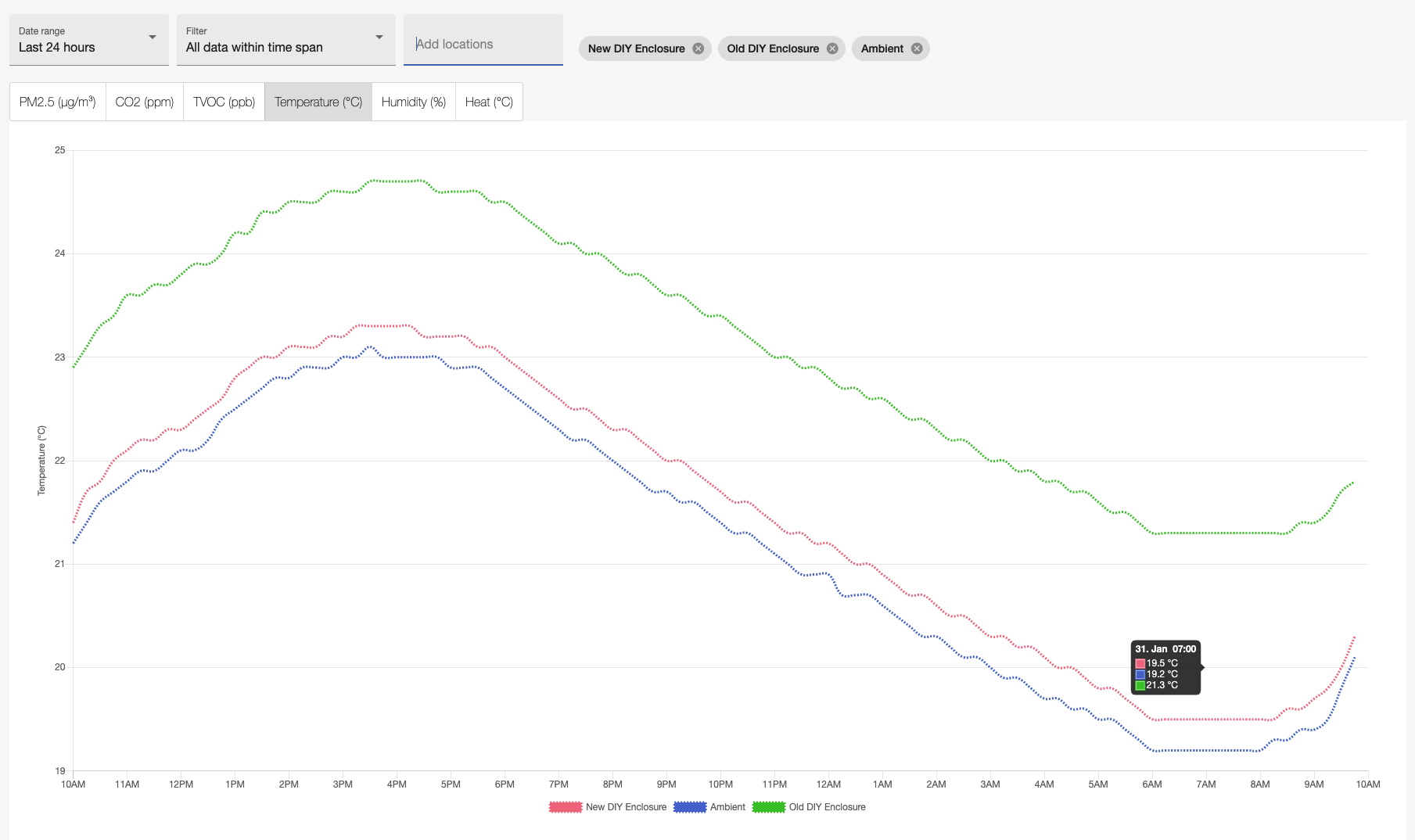
I am also running temperature measurements against the old DIY enclosure / PCB (without the external temperature probe) and you can see that we are now only 0.3C above ambient air temperature whereas the old enclosure is 2.0C above.

I will keep you posted. If you have any further feedback, questions or ideas please let me know.

6 Likes

I love all of this!

Having the breakout pins be compatible with regular headers will be a very welcomed improvement
I like the option for the PMS that fits the standard cable. Will your kits have the option to have a socket that could be soldered to the board, or will that be up to the DIYers?

Not sure what you mean with cable as the ESP8266 also has the charging cable. Have you looked at the Wemos S2 mini? It has the same size as the Wemos D1 mini currently used but is an ESP32 S2. According to the documentation it is also compatible to the Wemos D1 mini shields. So it might be a simple drop-in replacement.

The new housing seems to be big enough to potentially also add a battery and a TP4056 Lithium Battery Charger and remove the need for a constant power supply. Assuming that no OLED or LEDs are installed at the same time.

1 Like