My own enclosure

I have made some small updates.
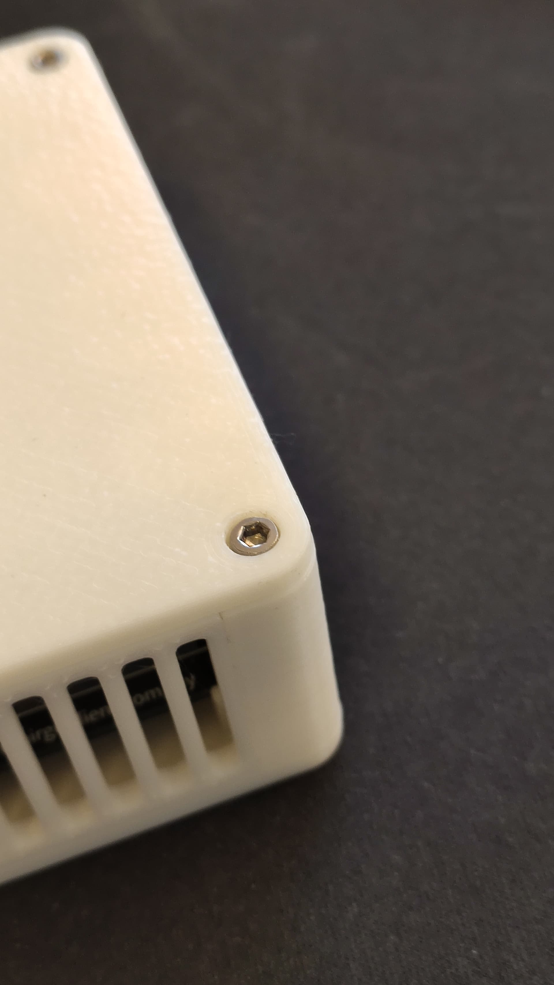
Moving the screws to the bottom is a bit more complex than expected and is still on the todo list.
It is ofcourse a matter of preference. Having the screws on top is more convinient for assembly.

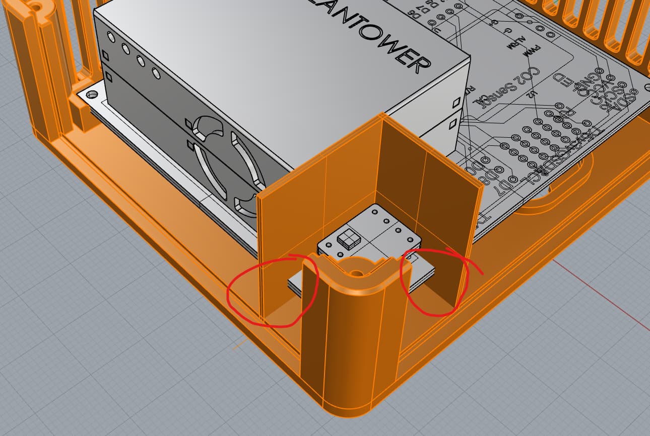
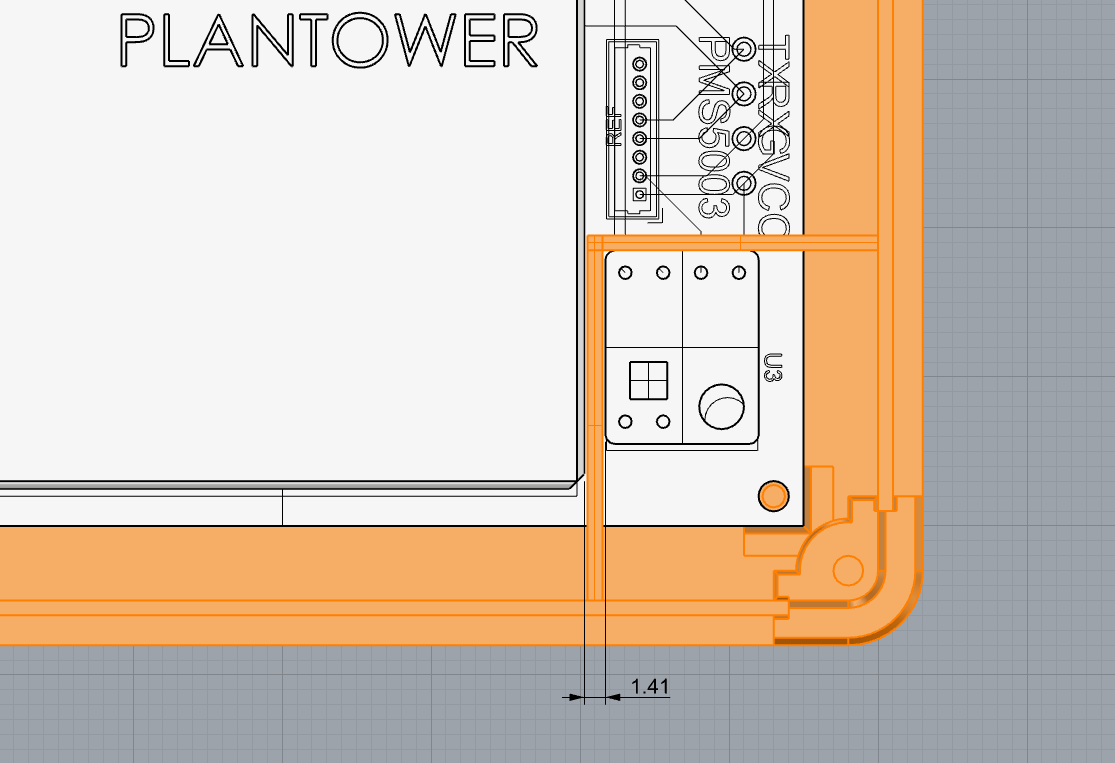
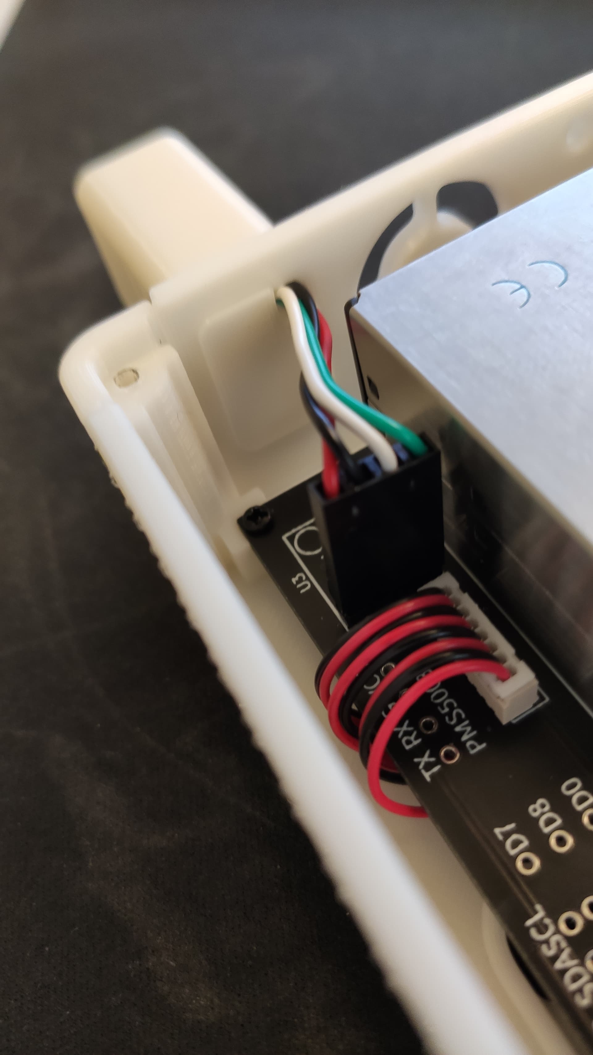
In order to compensate somewhat the “temperature leaking” I have added two new elements with a 20mm and 30mm extension for the SH3x.

I share now the folder instead of the files so that updating is more convinient.

https://drive.google.com/drive/folders/18hyBFjyJzBdfCH8klpFMiMLU_LZll0Xh?usp=sharing


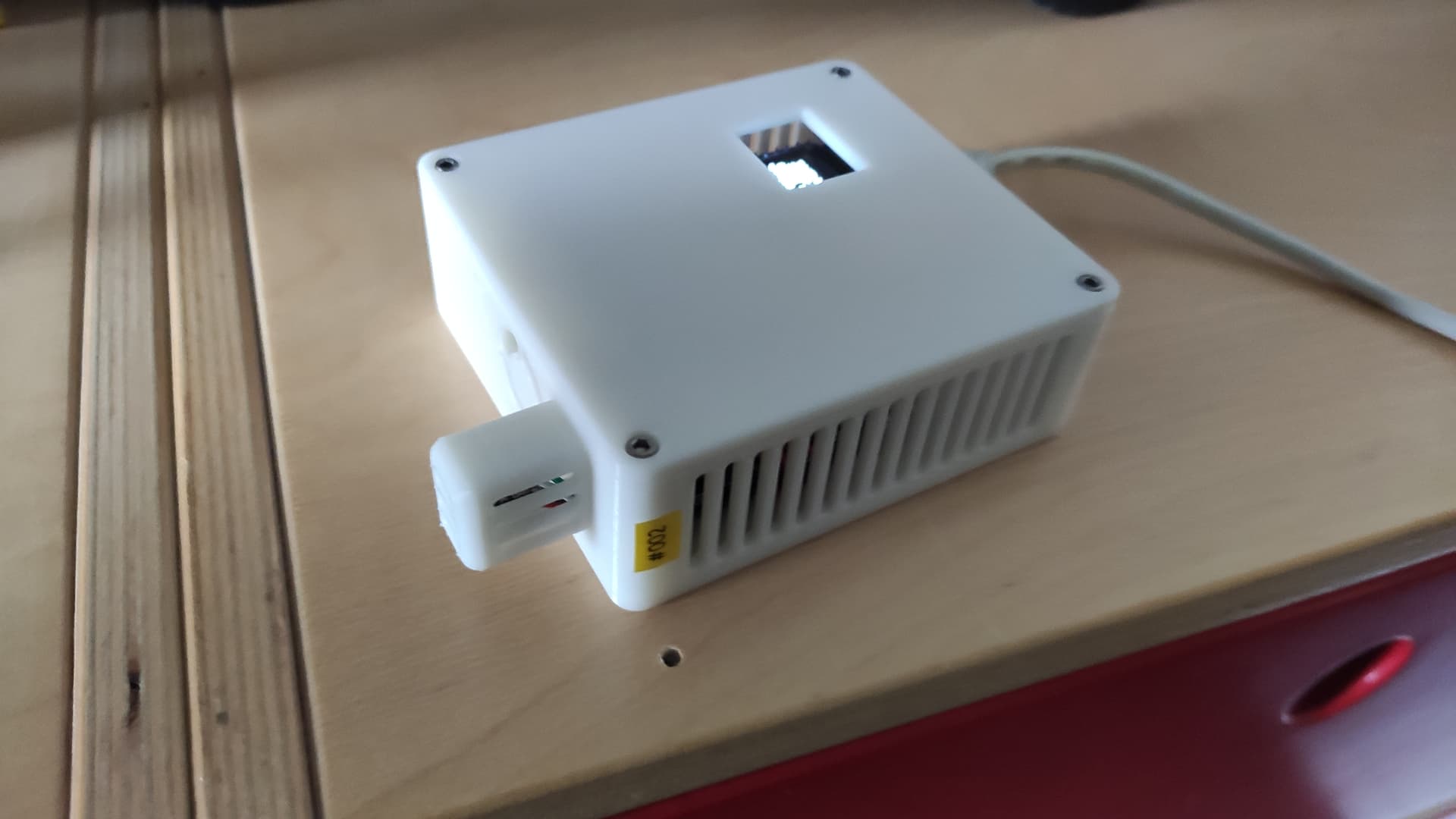
BTW what works nicely is the concept of the replacable sides. I can now swap out the sides without the need to reprint the whole case.

1 Like

nice case and no risk of breaking the probes clips during instalation! i do like the idea of separating the temperature sensor from the rest, but having it stick out of the case doesn’t look clean. so my idea would be to have it as a chamber inside the case itself with big ventilation slots to the outside of the case only. but no openings towards the inside besides one small hole where the cables can be fiddled through before soldering. afterwards that hole can be sealed with some hot glue or so. thoughts?

@dominic I just had a quick look at your suggestion. The distance between the PM and temperatuur sensor is just 1.4 milimeter. Even with a wall thickness of 1.0mm, the tolerances are small. The areas where the PCB crosses the walls can also be a bit tricky to get closed enough to have any effect.

What would interest me is where the heat is created. Is there somebody in this group with a thermal camera that can make some pictures of the airgradient? Maybe there are other areas of the PCB that are less influenced by other components.

We did extensive testing. The heat is generated by the PMS module and then conducted mostly through the PCB to the temperature sensor.

I also experiences with a small wall but it did not help much. This is why we have in our professional sensor and the new DIY kit that I am currently designing a big air gap between PMS and temperature sensor.

I do not think you can get an accurate temperature reading inside the small and current compact DIY sensor.

I just looked up our old testing for our professional sensor and have to slightly correct above.

Most heat is generated by the S8 and D1. However, since the PMS sensor is metal it conducts the heat much better and acts as a kind of transfer towards the temperature sensor.
Here is a thermal image we did at that time:

and here is a comparison of having the PMS powered off on the PCB vs off the PCB:

As I mentioned earlier we did extensive testing and one of the reasons why our professional sensor is bigger is that we just need the physical space for the separation of the components to achieve an accurate temperature reading.

I have a small question regarding your files: What is the purpose of the part “Plug for probe”? I opened it in an online 3mf viewer and could not really make sense of it.

I made it to close the hole to minimize potential heat transfer. It is force fitted in place (no glue required).

1 Like

@ttielemans I like this case! Would it be possible to get a version of the top without the lcd cutout? Thanks!

I mounted the PM sensor with VSB tape rather than screws, I wonder if that will help with the heat transfer issue… Perhaps even block some of the heat from the CO sensor…

@byrnespj Hi, I have added “Top side without LCD hole” in the google drive.

@Indymx Hi, I have build various cases. The best solution for the most accurate temperature reading is using the temperature and humidity sensor of the PMS5003T . Second best option is a case with the temperature sensor in the side with the extension.
Accroding to my experience, the impact of the case is rather low.
Do you have any measured deviations with the taped solution (measurement with the sensor and a reference thermometer)?

I have not done that yet. I haven’t put anything in a case yet either. I have an assortment of other temp sensors laying around, I’ll wire one up to another esp32 and sit in near the sht31 but with a few inches of air gap and let that sit for a while grabbing data and see what the difference over time is.

@ttielemans Thank you!!

I am not finding the 3mf files for the U-shaped pieces that bridges the gaps between the case and the PM sensor. Could you also post them or point me where to get them?

Sorry, I somehow missed that and also overlooked your message. I added them to the drive name “Air Tunnel Small.3mf” and “Air Tunnel Large.3mf”

Thanks for @ttielemans for the case! I’ve made some mods of my own and posted them on Printables. Made a sliding cover, magnet holes, and a top panel for the traffic light LED panel.
https://www.printables.com/model/178230-airgradient-diy-sensor-case-with-upgraded-sliding-

@captainpotato Very nicely done. I like the sliding cover. My son and wife were complaining about the brightness of the OLED and this would solve it.

socket

where did you get the socket for this plug? i would like to get one as well… what type is it?

MICRO JST 1.25 8Pin should work

In case anyone searches this while looking for an enclosure, this works with the v4 version of the PCB (or at least it did for me)