Trying to integrate an SPS30

I’m not sure this is allowed here because it deviates from the default hardware configuration but I’m stumped and hoping someone with more of a background can help.

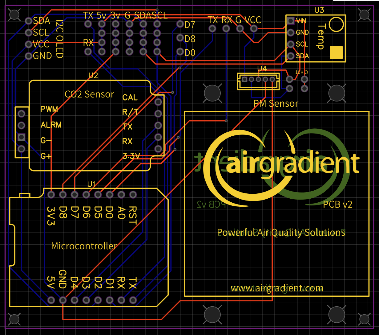
I’m trying to integrate the SPS30 sensor in place of the PMS5003. I’ve read all about pull-up resistors and designed and built the below but I’m getting what I think is an i2c bus conflict. U4 below is a header that connects to the SPS30. It may also have something to do with my limited understanding of pull-up resistors. Can anybody offer me any guidance?

My results are as follows:

[sps30:091]: Unable to read sensor firmware version
I get garbled text on the OLED
The sensor seems to get abnormally hot (resistor issue?)

The PMS5003 uses UART and not I2C. So if you like to run the SPS over I2C you would need to connect it tp SDA/SCL ports, e.g. on the top left. But you need to check the voltage requirements.

Yep, I managed to get that far and I think my PCB reflects the correct connections. Still no joy.

Is the SPS looking for 5v or 3.3v? Are you reusing the Temp header now, or how are you connecting it to the I2C?

according to the datasheet it’s 5v. I’ve connected it to I2C by way of a JST header. I think my issue is with the way i have the pull-up resistors connected to the SDA/SCL pins and my lack of understanding of how that should be connected.

I don’t have much experience with the SPS. But did you try and see if the SPS works without the other sensor modules connected?