Tip: use painters tape as temporary case closure

Unscrewing & rescrewing the AirGradient case takes time and, repeated, may strip the plastic threads.

I suspect I’ll be doing more firmware modifications in the near future since I don’t have the NOx up an running and my AG is frequently rebooting as many have discussed in another thread. But I don’t like leaving the hardware uncovered. So I use painter’s tape as a relatively secure but easily removable means of fastening the case.

I’m in a similar boat and have just left the back off but I can’t see the display, so I may do this.

We experienced similar thing and we have already changed the screws to stainless steel TORX screws. So this should not happen in future anymore.

Thanks Achim - just to confirm, the new Torx screws shouldn’t strip the plastic receivers? I have those.

I don’t understand. What do you mean with plastic receivers?

In the case. I.e. the screw holes.

Should not and we use them quite heavily also on our commercial version of the monitor.

We custom made these screws because we did not find the exact quality and size that we wanted on the market.

I will check if we can make them available in the shop with a low cost shipping fee.

2 Likes

After the first night of reboots, I’ve taken the back cover off and it hasn’t gone back on yet. Don’t want to strip the housing. I had a few thoughts:

  • Buy a short USB-C extension cable and have it permanently plugged into the D1 Mini with the female end coming out of the larger hole in the back.

  • Can’t we do OTA updates? I think there are some libraries that can do that. I’m brand-new to Arduino and the ESP microcontrollers, so I haven’t done enough research to know if there is something preventing us from doing this.

I know with ESPHome you can do OTA, but not sure about straight Arduino

@ken830 love the creative thinking! I ordered a 2m double end USB-C cable which I will thread through the larger hole to the board so I no longer have to take the enclosure apart, just unplug the other end from a power adapter and plug it into my Mac.

But yeah, I like the idea of your short male to female, and yeah - OTA would be great. The cable method’s there as a backup.

It looks doable from reviewing the first Google hit on “flash ESP8266 OTA”. Might try this Monday.

For future PCB designs: Would it not be possible to allow flashing through the USB port on the mainboard (as opposed to only allow flashing via the USB port on the D1)?

With only 2 weeks of experience with the AirGradient and ESP/Arduino/D1 Mini, I may not fully understand everything, but from the quick glance I had at the schematics two weeks ago, it’s not feasible with a stock D1 Mini v4.0 board.

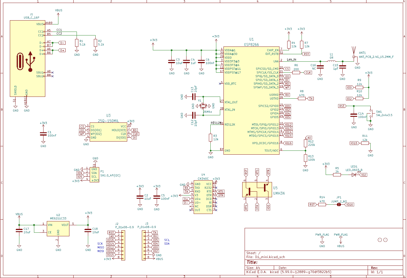
If you haven’t already, take a look at the schematics provided by wemos.cc: https://www.wemos.cc/en/latest/_static/files/sch_d1_mini_v4.0.0.pdf

The ESP8266EX uses its hardware serial port to connect to the host. The USB-to-Serial conversion is done by the CH340C IC. To put the ESP8266EX in programming mode, the RTS and DTR output from the CH340C needs to control the GPIO0 and the RESET pins. This is done with two transistors (UMH3N).

From the D1 Mini’s headers, we have access to the RX and TX pins as well as the GPIO0 and RESET pins. Great! But hang on! The problem is you can’t just put in a parallel circuit with another set of CH340C + transistors. There will be contention when multiple outputs are driving the same line. You’ll need to disable or remove the CH340C from the D1 Mini board.

The easier way, if we’re redesigning the PCB might be to put two USB-C Female connectors on the PCB and plug in a short USB-C (standard male-to-male) cable from the the D1 Mini’s USB-C port to the PCB, which serves as a passive passthrough extension.

1 Like

Yes we also looked into this and came to the same conclusion like @ken830.
However down the road we are considering to make an updated DIY pro board with an esp 32 c3 module directly on the board.

The C3 is interesting as it has built in flashing capabilities.

With this redesign we could then also use two separate hardware serials for S8 and PMS and even move the OLED display to SPI to unload the i2c bus a bit.