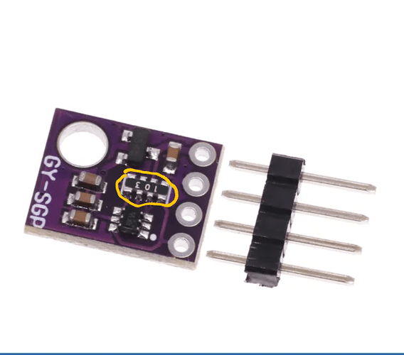
I bought this SGP41 and wondered if i need to remove the 103 resistor
My understanding is that you should only have one set of pull ups, the SHT sensor has pull ups, and the LCD has pull ups as well, but using both unmodified has been fine.
It’s adding more than that that has been problematic. On my board I actually modified all of the sensors and left the pull ups on the LCD only. Build is working 100%
Do note that if you’re using the SGP41, that you use the correct code for the SGP41, earlier versions of the example code use the SGP30, and the library is different.
Ok i found out the easiest would be to remove the resistors on the sht. Thanks for the info!
I’m guessing I’m only removing them on the sht, no need to connect the lines afterwards on the sht board since there’s going to be missing resistors.
The resistors are there to “pull up” SDA and SCL to VCC, the resistors aren’t inline on the SDA/SCL lines, so you don’t reconnect anything after removing them (on any sensor).
Ok cool, thanks for the info!
