AirGradient Forum

OLED doesn't work on my DIY Basic Kit

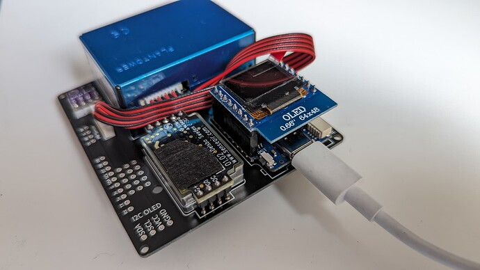
I assembled the DIY Basic kit and flashed D1 Mini with Air Gradient firmware using the simple flash method via a browser (the button from the instructions website).

When I plug it to power, OLED never shows up with any information. After I flashed D1 Mini, I followed the instructions to connect it to my wifi and it connects correctly, I can ping it on my local network.

I also tried flashing the firmware using PlatformIO and AirGradient library. Same issue.

I double checked that OLED pins are properly connected to the D1 Mini with use of the multimeter. Every pin has the correct connection.

I’m guessing everything works fine, but the OLED seems broken?

Link to video and more pictures https://photos.app.goo.gl/NkUxCfXqFaLtRvYv6

Can anybody help diagnose what the problem is?

I added it to the Air Gradient Dashboard, but no data shows up, so maybe there is an issue with D1 Mini.

I also used Arduino IDE to get the serial output from D1 Mini.

*wm:Connecting to SAVED AP: <redacted by me>
*wm:connectTimeout not set, ESP waitForConnectResult... 
*wm:AutoConnect: SUCCESS 
*wm:STA IP Address: 192.168.1.148
CO2 Successfully Initialized. Heating up for 10s
-3
-1
0.00
{"wifi":-64, "atmp":0.00, "rhum":0}
http://hw.airgradient.com/sensors/airgradient:65f6f6/measures
400
sensor 'airgradient:65f6f6' unknown
-3
-1
0.00
-3
-1
0.00
{"wifi":-64, "atmp":0.00, "rhum":0}

It connectsto wifi successfuly, but then it has the “sensor … unknown” message.

Ill add that i’m facing pretty much the exact same issue with my Basis kit at well. OLED is not displaying anything at all, D1 is able to get power and connect to Wifi, and shows up in dashboard, but with no readings besides a bad temperature reading. Overall board looks to be getting power as the CO2 sensor blinks.

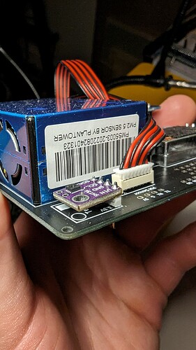
Can you please send a clearer picture how you connected the SHT sensor on the board?
Normally we recommend using the female pin headers and not solder directly on the board. This makes debugging quite difficult now.

Sure, here’s the picture. I also added more pictures to the google photos album linked in my first post.

Normally we recommend using the female pin headers and not solder directly on the board

You mean for SHT? According to the Soldering The SHT30/31 Module (Temperature and Humidity) section, soldering is recommended

@Mateusz I have built the same kit this weekend just to check if there is any fundamental issue but it was running with everything working on the first try. Display worked just fine.

I also checked your photos again and cannot see any problem.

Can you provide a longer debug log (at least 2 minutes of operation)

What happens if you disconnect the PM sensor?

Sure, here’s a 2 minute log. It loops with the same data non-stop.

*wm:AutoConnect 
*wm:Connecting to SAVED AP: <redacted>
*wm:connectTimeout not set, ESP waitForConnectResult... 
*wm:AutoConnect: SUCCESS 
*wm:STA IP Address: 192.168.1.148
CO2 Successfully Initialized. Heating up for 10s
-3
-1
0.00
{"wifi":-68, "atmp":0.00, "rhum":0}
http://hw.airgradient.com/sensors/airgradient:65f6f6/measures
400
sensor 'airgradient:65f6f6' unknown
-3
-1
0.00
-3
-1
0.00
-3
-1
0.00
{"wifi":-68, "atmp":0.00, "rhum":0}
http://hw.airgradient.com/sensors/airgradient:65f6f6/measures
400
sensor 'airgradient:65f6f6' unknown
0.00
0.00
0.00
0.00
0.00
-3
-1
0.00
0.00
-3
-1
0.00
{"wifi":-67, "atmp":0.00, "rhum":0}
http://hw.airgradient.com/sensors/airgradient:65f6f6/measures
400
sensor 'airgradient:65f6f6' unknown
0.00
-3
-1
0.00
0.00
-3
-1
0.00
{"wifi":-68, "atmp":0.00, "rhum":0}
http://hw.airgradient.com/sensors/airgradient:65f6f6/measures
400
sensor 'airgradient:65f6f6' unknown
0.00
-3
-1
0.00
0.00
-3
-1
0.00
{"wifi":-68, "atmp":0.00, "rhum":0}
http://hw.airgradient.com/sensors/airgradient:65f6f6/measures
400
sensor 'airgradient:65f6f6' unknown
0.00
-3
-1
0.00
0.00
-3
-1
0.00
{"wifi":-71, "atmp":0.00, "rhum":0}
http://hw.airgradient.com/sensors/airgradient:65f6f6/measures
400
sensor 'airgradient:65f6f6' unknown
0.00
-3
-1
0.00
0.00
-3
-1
0.00
{"wifi":-69, "atmp":0.00, "rhum":0}
http://hw.airgradient.com/sensors/airgradient:65f6f6/measures
400
sensor 'airgradient:65f6f6' unknown
0.00
-3
-1
0.00
0.00
-3
-1
0.00
{"wifi":-68, "atmp":0.00, "rhum":0}
http://hw.airgradient.com/sensors/airgradient:65f6f6/measures
400
sensor 'airgradient:65f6f6' unknown
0.00
-3
-1
0.00
0.00
-3
-1
0.00

Below are logs when I disconnect the PM sensor. Looks identical:

*wm:AutoConnect 
*wm:Connecting to SAVED AP: <redacted>
*wm:connectTimeout not set, ESP waitForConnectResult... 
*wm:AutoConnect: SUCCESS 
*wm:STA IP Address: 192.168.1.148
CO2 Successfully Initialized. Heating up for 10s
-3
-1
0.00
0.00
-3
-1
0.00
{"wifi":-68, "atmp":0.00, "rhum":0}
http://hw.airgradient.com/sensors/airgradient:65f6f6/measures
400
sensor 'airgradient:65f6f6' unknown
0.00
-3
-1
0.00
0.00
-3
-1
0.00
{"wifi":-67, "atmp":0.00, "rhum":0}
http://hw.airgradient.com/sensors/airgradient:65f6f6/measures
400
sensor 'airgradient:65f6f6' unknown
0.00
-3
-1
0.00
0.00
-3
-1
0.00
{"wifi":-68, "atmp":0.00, "rhum":0}

I looked again on all your photos but really cannot make sense of it. Please contact our support. We will send you some free replacement parts.

Hi again,

Just an update on this thread.

I received a spare D1 Mini, flashed it and soldered it to my existing PCB. Upon powering up, everything now seems to work, which indicates that the previous Mini must’ve been faulty.

Thank you for sending the spare parts and for the support!