[HELP] Only getting CO2 Sensor readings

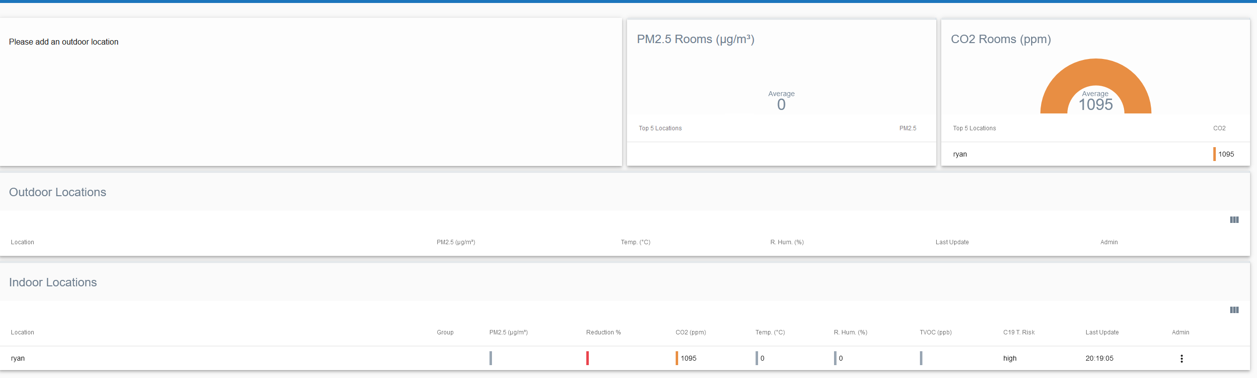
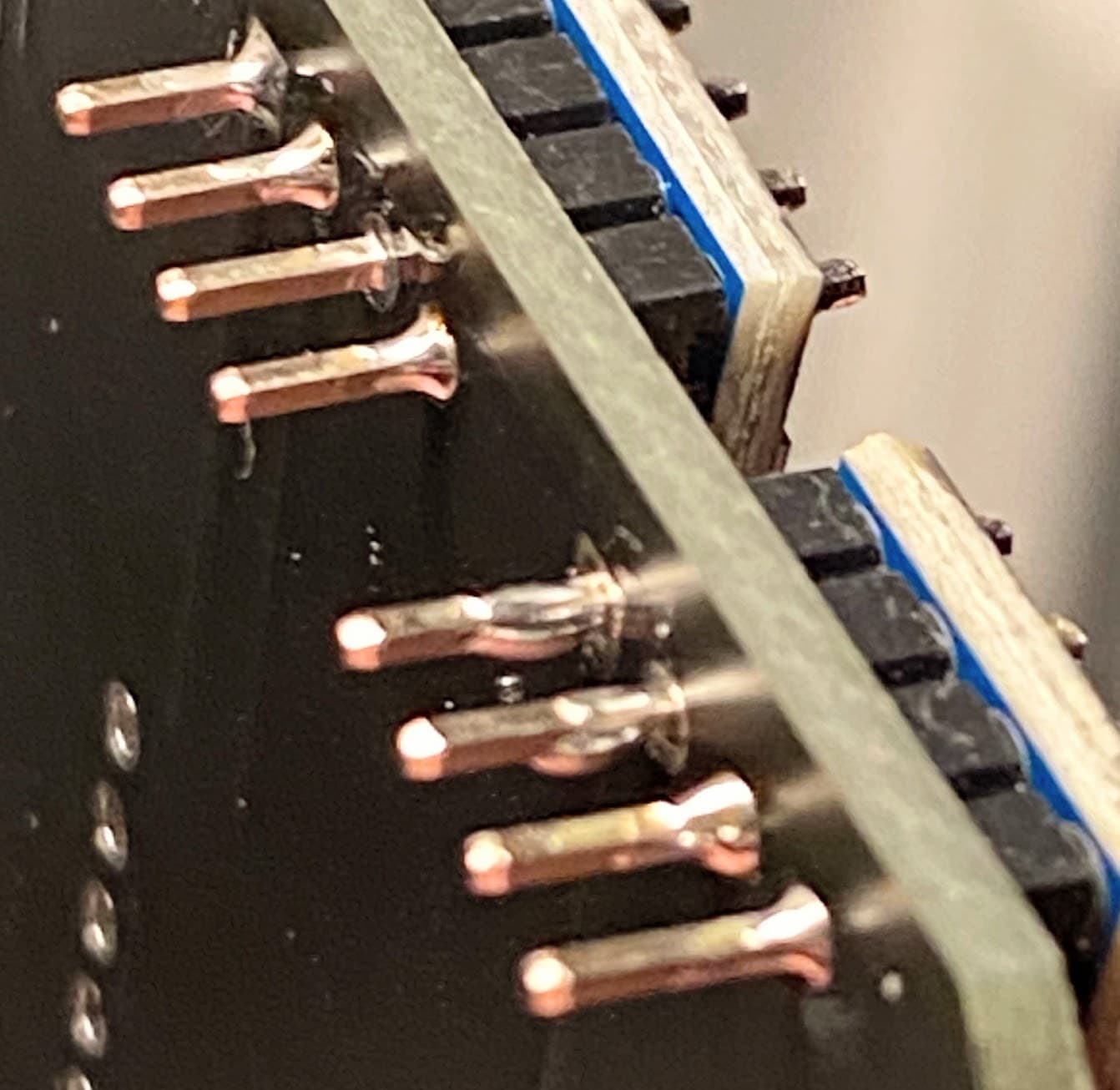
I just soldered everything and all the solder looks good. I uploaded the AirGradient Pro + TVOC firmware and set up the dashboard but I’m only getting the CO2 readings and the website (http://hw.airgradient.com/sensors/airgradient:c0239e/measures) does not work, I get a “Cannot GET /sensors/airgradient:c0239e/measures”.

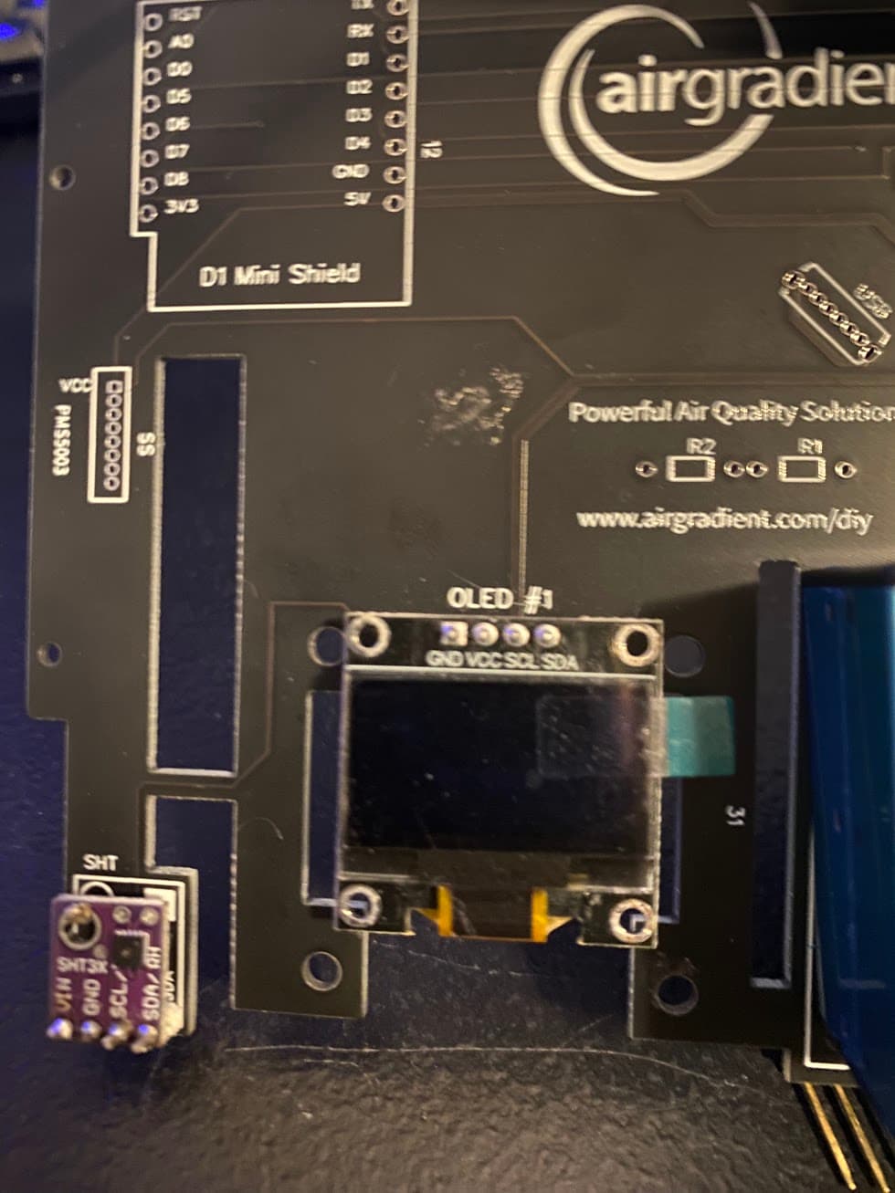
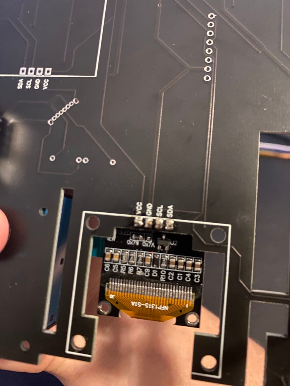
There is nothing on the display and I have re-flashed the firmware several times. I have tried this with 2 different OLED screens and with 2 different computers.

The logs are here, *wm:[2] Connection result: WL_CONNECTED*wm:[1] AutoConnect: SUCCESS *wm:[2] - Pastebin.com.
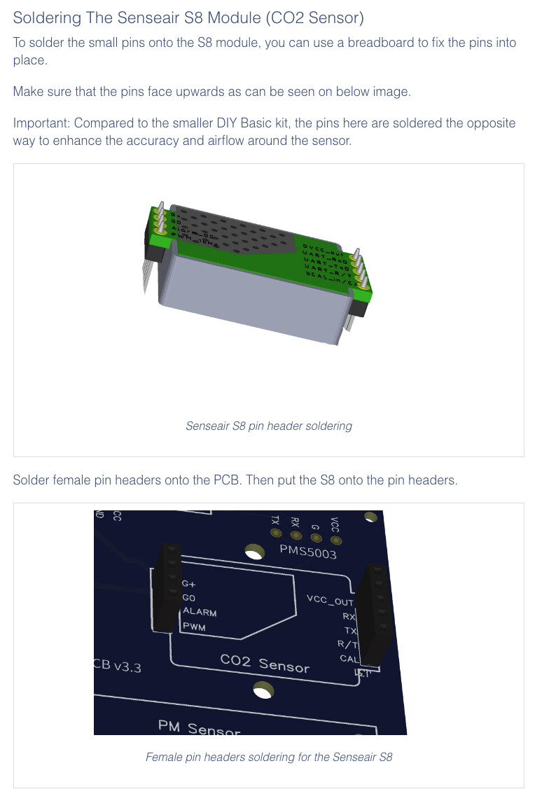
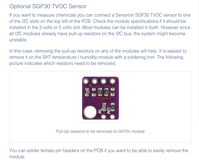
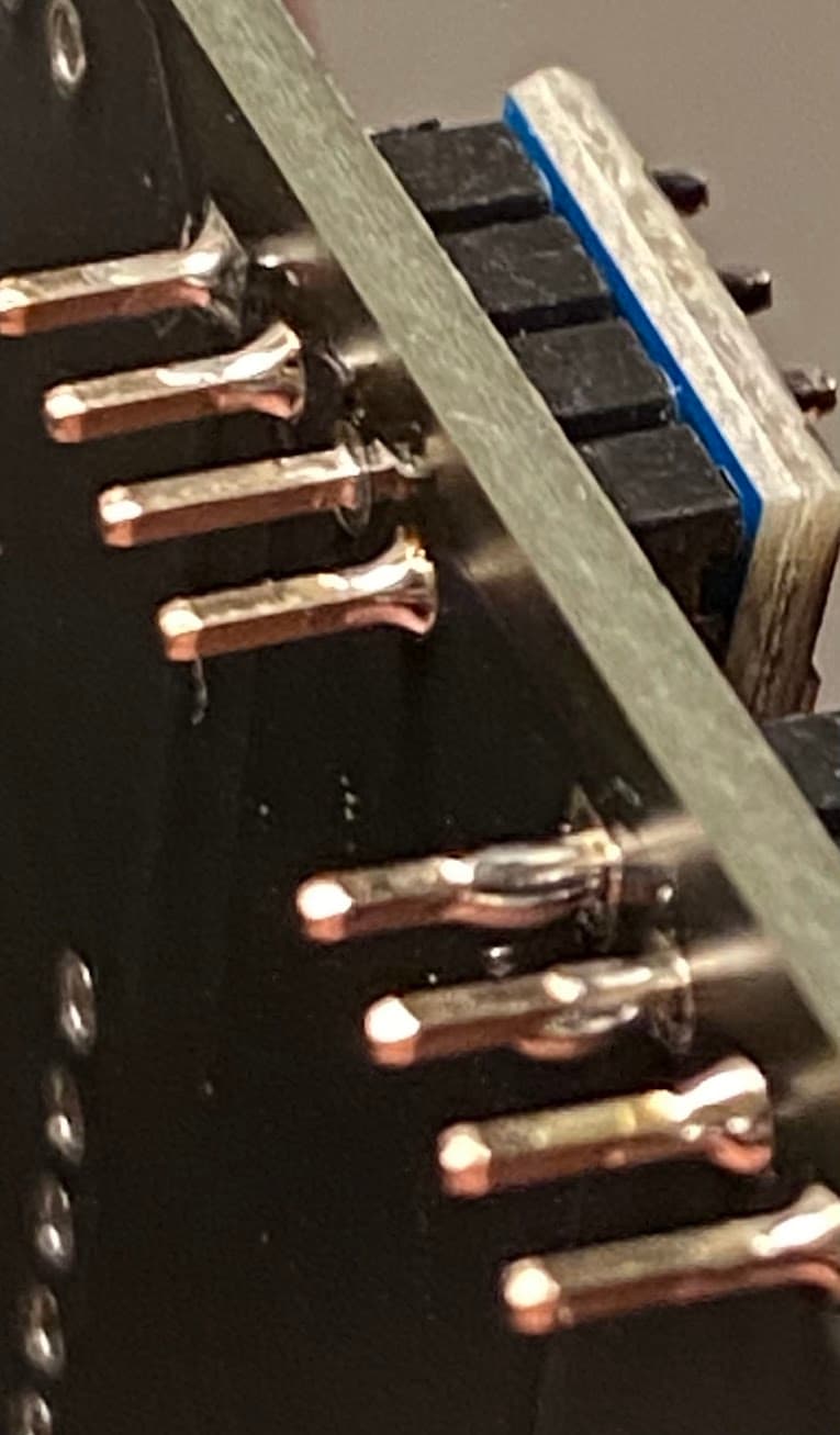
Here’s some pictures of my soldering, https://imgur.com/a/yYXQtyZ

Please post some images from both sides of the pcb.

https://imgur.com/a/SRr6dv3
I uploaded some more photos

Ok, there are a couple of issues:

a) The CO2 sensor should be on the opposite side of the board with reversed Pins but that probably does not cause the issues. See The AirGradient DIY Air Quality Sensor (Pro Version)

b) You probably have too many devices on the i2c bus and you need to remove pull up resistors. See The AirGradient DIY Air Quality Sensor (Pro Version)

c) Check if the pins of the BMP180 match the PCB labels (cannot see from your image)

I would recommend next time you solder the sensors, use female pin headers for all of them. This makes it much easier to debug problems.

So for the first one, I’m aware it’s supposed to be on the other side but I didn’t want to de-solder it after I put it on so I just left it.

The second one, it says it “will help” my SGP30 sensor, the sensor description can do 2 - 5V so I put it in the 3V slot, I don’t think my soldering iron is small enough for the resistor.

Third, I have confirmed that the BMP sensor matches the PCB’s pinout.

I looked a bit more and found some questionable solders on the BMP and SGP30 sensor, if this is soldered incorrectly, would this affect the SHT3x or other sensors?


I think that the bmp module probably also has pull up resistors. This will make it much less likely that the whole i2c bus works. I would suggest you desolder SHT, SGP and bmp and put female pin headers there. Then try each one first individually and see if they work.

thank you for your replies, I resoldered the things shown in the picture above but still no luck. For unsoldering the 3 sensors and putting female pin headers on them, is there one I should unsolder first that would most likely be the issue?

I think the OLED is mounted the wrong way and creates shorts on the pins.

1 Like

I think your right!!! The pin layout on the PCB is different than how it’s put in!!


I just broke the D1 Mini I had trying to make the OLED screen work on a breadboard… Before it stopped working, it gave me the TEMP and the HUMIDITY levels! So you were right about the OLED screen, as soon as I took the OLED off it started working. I’m going to order some new parts (OLED + d1mini) and get a better soldering iron and some better solder. It also turns out that the solder I was using was way too thick and did not have a rosin core.

I appreciate your help, hoping to try again when some new parts arrive.

To anyone who may encounter my problem in the future,

  • Make sure the CO2 Sensor is on the correct side of the board and do a test placement before soldering

  • Make sure you remove the resistor from the TEMP&HUMID, TVOC & BMP sensors for best results

  • The OLED screen goes on the back and not the front, and that some OLED screens have a different pinout (including mine) than what is on the PCB.

  • You don’t need to use the USBC header on the PCB if your microcontroller already has one