Feedback on new 3D printable Enclosure

We have recently published a new version of the AirGradient DIY enclosure.

Information and STL files are available here:

https://www.airgradient.com/resources/the-airgradient-diy-sensor-enclosure/

image

The main improvements we wanted to achieve were:

  • An (optional) external temperature probe for more accurate temperature measurements
  • Integrated wall mounting holes

We are interested to hear your thoughts about the redesign and any future improvements you might have.

3 Likes

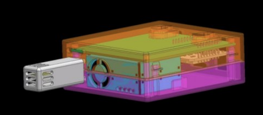
I’ve just managed to get the board mounted in the new enclosure, but it was not without a challenge.

The way I approached the assembly was to first snap the PM sensor into its guides in the lid, as that was a firm fit. (Intuitively to me that seemed the first step).

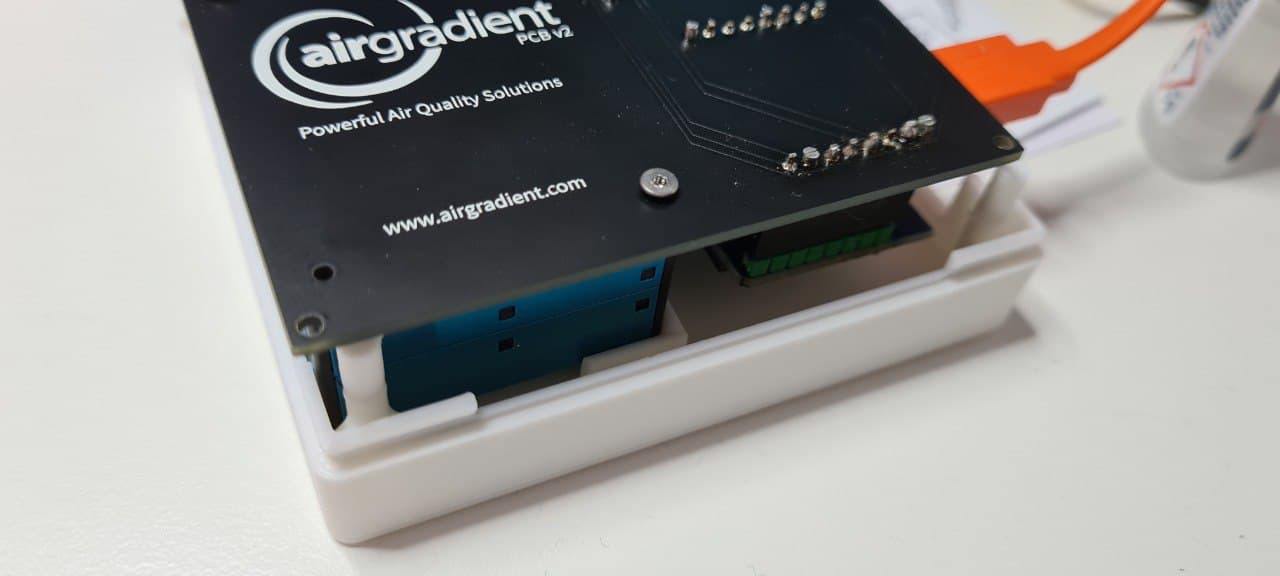
That meant that the PCB then ‘floated’ on top of it until you can bring the base close enough for its tiny pins to align with the holes in the PCB. To do this I had to close the base as far as it would go, then ‘cajole’ the board into place using a tiny screwdriver poked through the ventilation holes. Once they aligned the enclosure snapped closed nicely.

So the ONE change I think would be really helpful would be to move the tiny pins that keep the PCB in position onto the “lid” not the base.


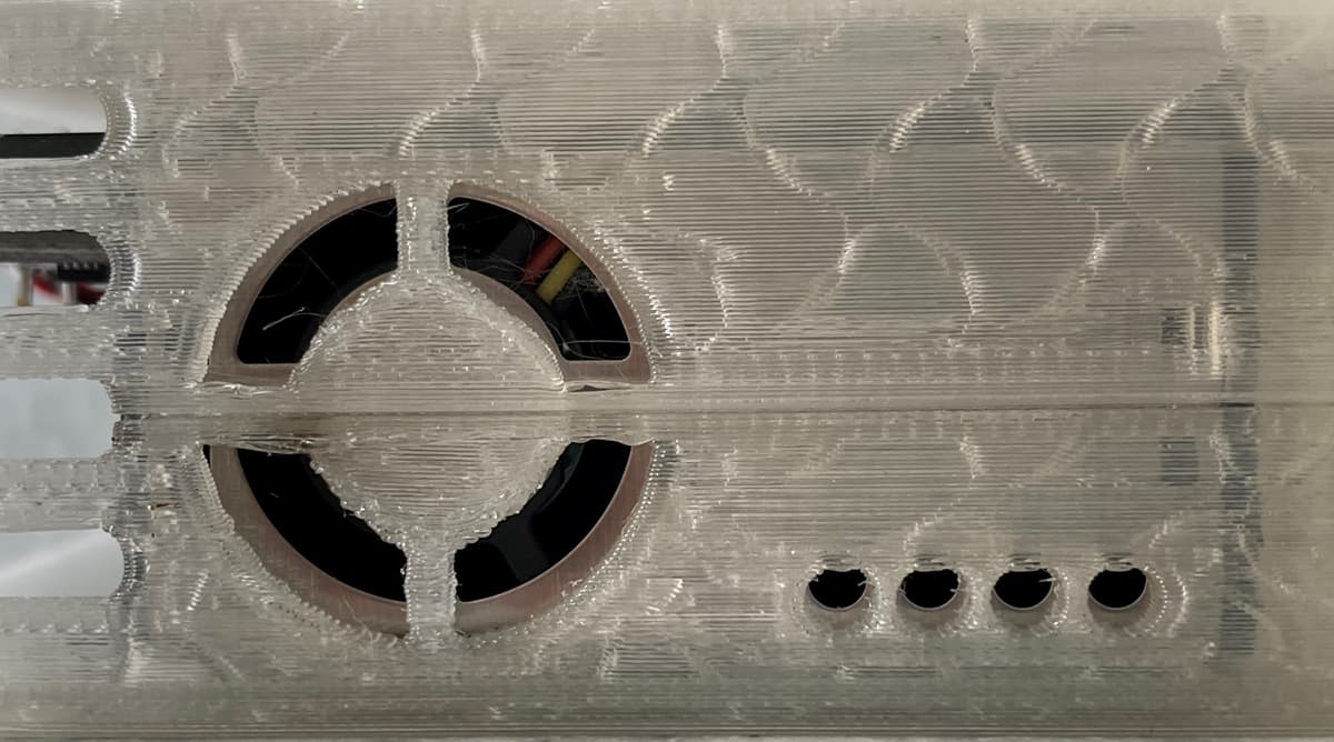
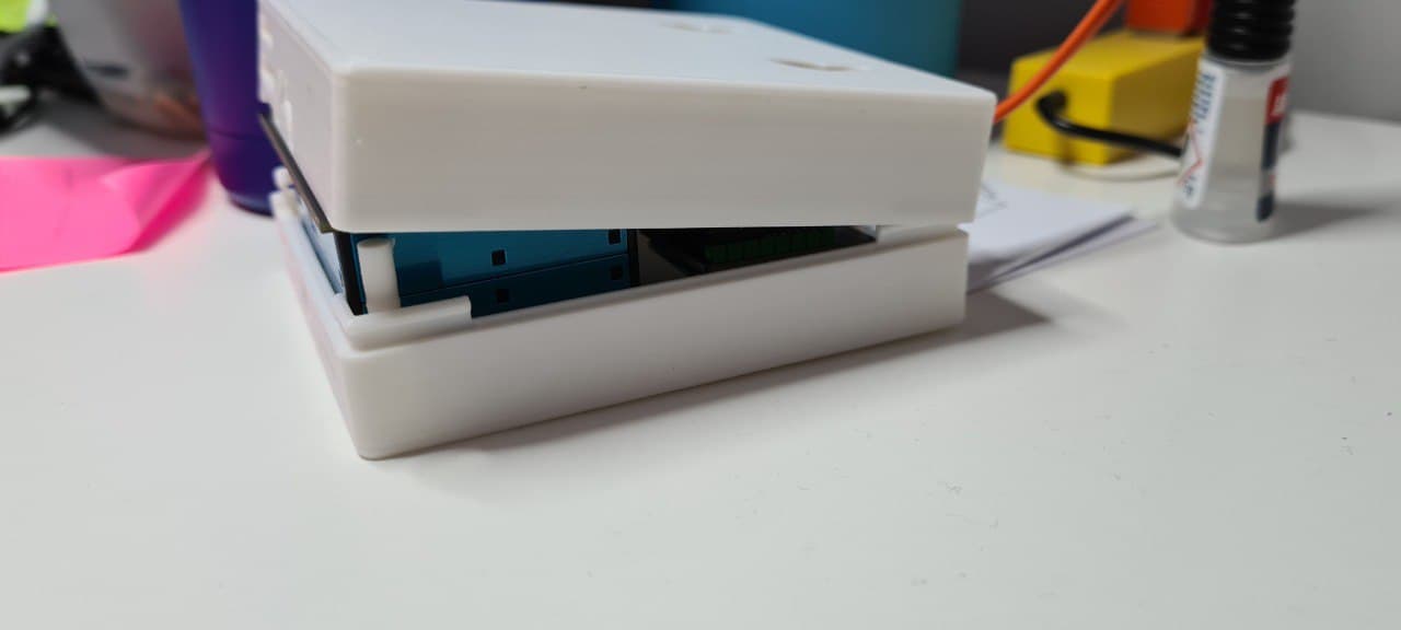
This isn't necessarily a box issue, but I'll also need to crack it open again soon and put some kind of 'spacer' between the board and the PM sensor, to make sure the sensor is pushed fully against the lid of the enclosure. The little bit of free movement it has means its ventilation and fan holes don't align 100%. (MAYBE a printed clip in the enclosure can ensure it's held snug to the lid?


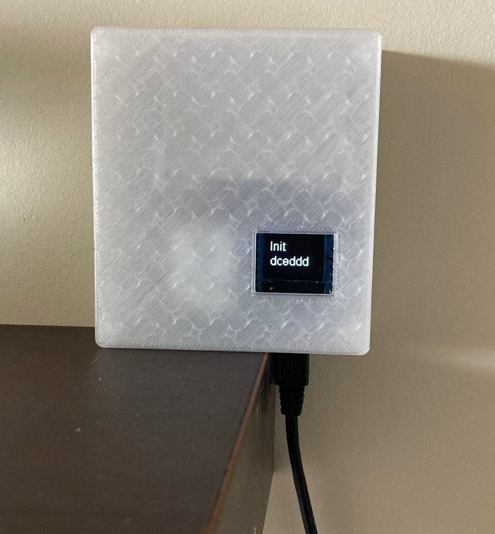
All-in-all, it’s a nice, neat little enclosure so far, but as always with these things, we could be gilding this particular lily forever.


- Greig.

Have I done something wrong here or are the keyhole slots upside down? (I realise you can flip the display in code, but I don’t want the power cable sticking out the top).


- Greig.

Greig, thank you for the feedback. Let’s collect feedback from others here and once we have a number of improvements I will ask our designer to make an improved version.

1 Like

The power needs to come from the top and you need to rotate the display. It seems some displays have different chips and default rotations.

You can do that in your code. Just remove this line:

display.flipScreenVertically();

image

The reason why we have the power from the top is because we want the PMS sensor at the bottom in order to protect it from dust falling into it.

OK, I get you.

That makes some ense, however unfortunately the top photo on the /diy page shows it right-reading with the power at the bottom, so that probably needs correcting. Jeff’s video does too, and I appreciate that’s not as easily corrected.

Personally, my approach will be to either put a “falling objects” shield above it, or redesign the case in-house so that power continues to be fed in from the bottom, but the fan is either side-mounted or facing down. (Does the sensor actually require the fan mounted in any specific orientation?)

Whilst some might see the power input location as just an aesthetic thing, for me having it at the bottom is a safety feature. If anyone here (human or feline) snags the cable I want it to disconnect without damaging anything/anyone. Having the connector at the top means in this scenario something else would have to give.

And then there’s the aesthetics. :slight_smile:


- Greig.

1 Like

Hm… Mine defaulted to the same orientation as the original poster, I just assumed that was the way it was supposed to be. Power coming out of the top does seem more odd, as the cord will go up and around to come down to be plugged in, since I don’t have any right angle micro-usb cables.

I just saw the orientation on the official DIY page as well, so I’m guessing this is a recent decision. Maybe v3 can have it turned to the side if that is compatible with the PM sensor.

1 Like

Yes, good points for the next iterations. Let’s collect more feedback here on the enclosure. Maybe there are other things we can improve.

I had a friend print one for me and just got it today.

Would it be possible for the mounting holes to work either way, up or down, so we could choose which way to orient it?

I’m also confused about the temperature probe extension. I didn’t see a great place to click it into place, as it looked like there were regular notches for venting where the temp probe usually us, but no space big enough for the extension. Does it click between the vent slots so the cable only fits through a narrow spot? I was assuming there would be more of a general hole the size of the extension go fit into.

How do we get the temp board to the end of the extension? Just gravity held or some other trick?

The person who printed it for me tried fitting it together before giving to me and when he tried to take it apart one of the clips broke since they weren’t flexible. Is this intended to be a one-time install or maybe improvements on clip durability?

Yes the probe should click into the vents.

image

It works very well for me but might depend on the material used and maybe also the printer.

Yes, gravity should hold the SHT in place. For extra accuracy, it might also make sense to put a bit of foam onside the probe (above the SHT).

If the PM2 sensor is screwed-attached to the PCB - edge of PCB prevents top case cover from closing.


1 Like

I had the same problem with where I had tapped down my sensor, I had tried to line it up with the screw holes (sadly I used a really sticky 3M tape and can’t unstick it now!)

Good points with the screws. We added the compartment for the PMS sensor in the new enclosure so there is actually no need to screw it on (and the screws holes were for the old DIY case). So best is not to use screws at all and if you want to use double-sided tape, use a very thin one.

I commented the flipScreenVertically line. It displays with the correct orientation, but the bottom line is cutoff, it appears to have a margin at the top which pushes both lines down. Any idea of what is the issue?

@Richardg
search for following code and update the coordinates. not sure to which exact values but i assume you can find out yourself :wink:

  display.drawString(32, 16, ln1);
  display.drawString(32, 36, ln2);

it would be helpful to get some info on recommended printing settings.

this was my first 3d print and the service i used asked me so many questions of which none i could answer :smiley: 
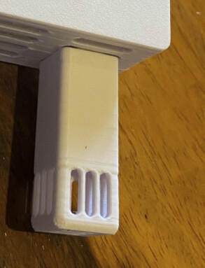
the case itself turned out nice but the temperature housing gave me lots of trouble with removing the support structure resulting in many of the fine structures in the top to break off. and when i tried to gently push it into the main case one of the little retaining clips snapped. it’s being hold in place by scotch tape for now.

Could you please let me know what specific settings the shop asked you for?

I just installed my temperature extension yesterday and I also broke off one of the clips in the process. I can’t reprint it right now, so I’ll have to tape it as well.

Yes it is something we definitely need to improve in the next iteration of the enclosure.
Thanks for the feedback!