Things like thickness of the nozzle, infill, if and how thick help structures should be and so on
I used 0.4mm nozzle and for the other things the standard settings from Ultimaker Cura.
What purpose have this hole ?
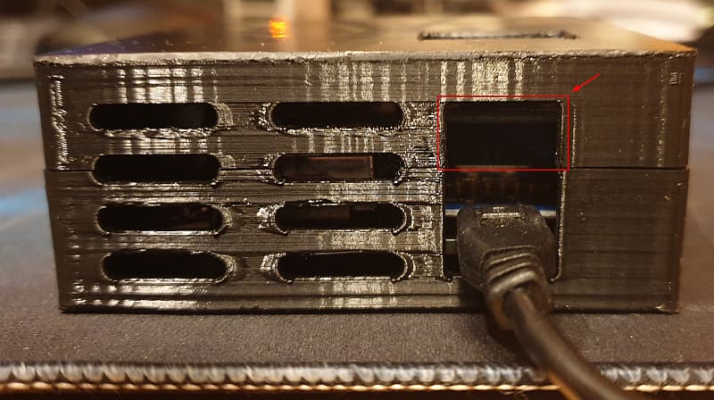
i can’t think of any use for that, i closed it in my second print.
the hole for the USB (Power) in the lower section is of course necessary.
There are mainly two reasons.
- some people mount the D1 on female pin headers. Then the USB port is a lot higher.
- you can put a battery shield above/below the D1 and then you would need both plugs accessible. One for flashing and one for charging.
1 Like
That makes sense to me. If I wasn’t using the OLED shield, I would certainly prefer to mount the D1 Mini on female headers to keep things modular.
Is it possible to get the 3D files for the case in another format? This is a mesh body and I’m not able to make changes to it. I added a TVOC sensor to my kit and it’s increasing my temp by about 2 Celsius. I want to try to add some airflow and see if it will help.
Thank you. I can work with this format. I will post the changes.
I think the note of not screwing in the PM 2.5 Sensor when using the case would be a good NOTE on the page below, figured it out pretty quickly but just cause im use to screwing things down was like HUH what happened 
also i needed the fix for vertical screen issue for anyone whos looking for a good estimate.
Commented out
//display.flipScreenVertically();
And my Changed lines to way i liked it are
display.drawString(32, 0, ln1);
display.drawString(32, 20, ln2);
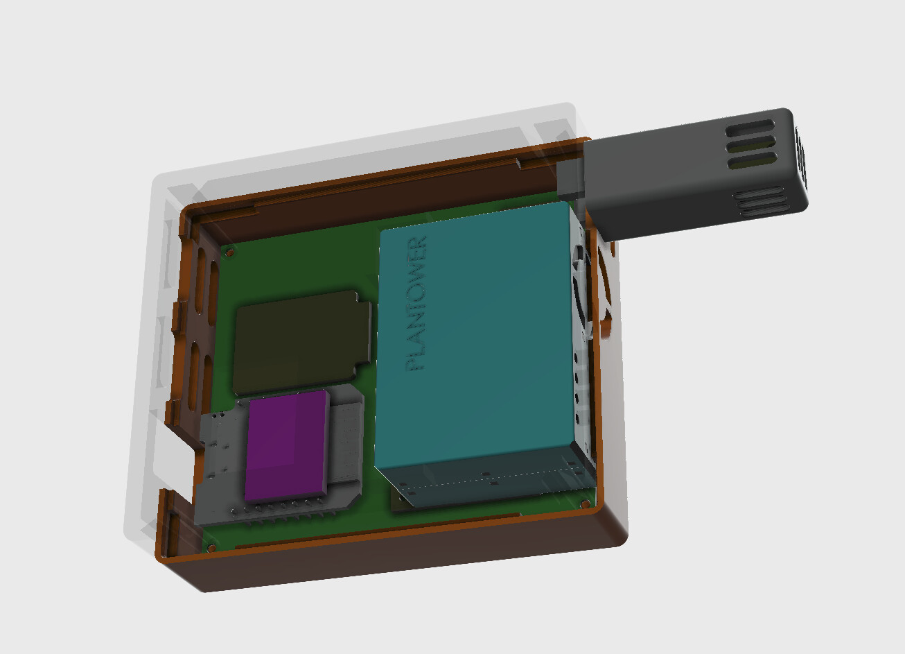
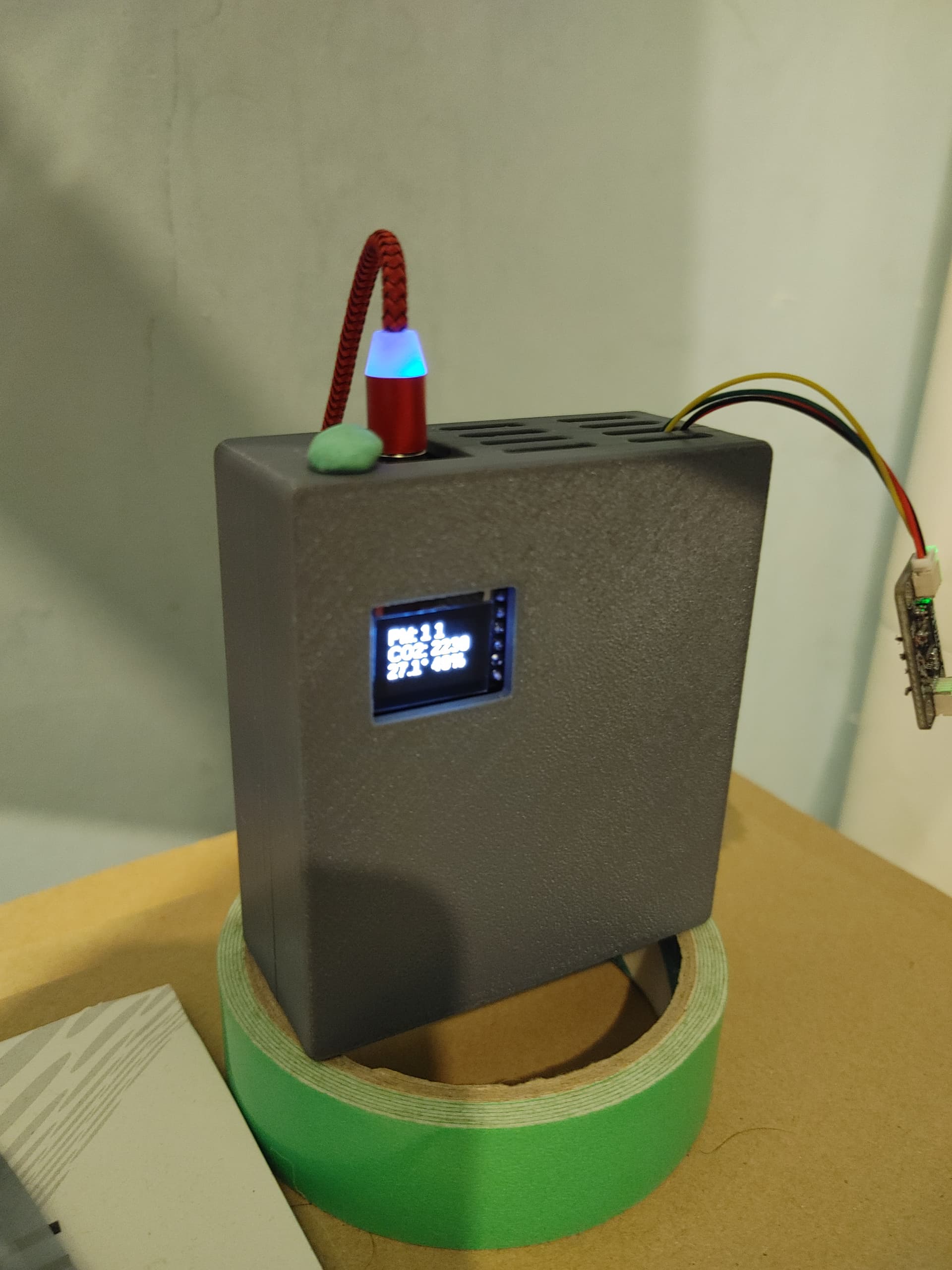
How does the temperature probe work? Do you just attach the SHT sensor to a few wires and then stick it down inside the probe casing (without mounting it; it’s just held in place by gravity as mentioned above)?
Yes this is the way exactly.
Quite note (esp for @AirGradientBlog ) this case doesn’t appear to fit the v4 PCB? I ended up using this one:
Might be worth updating the documentation to reflect the v4 case compatibility perhaps? I may have done something wrong but it seemed like the blue box didn’t line up with the ridges in the case for it. The above one works well though. Only minor downside is it does require screws though I happened to have some M2’s (pretty sure they are M2s) and those seemed to work well.
I am not aware we moved the PM sensors. Could you please post some photos with the misalignment?
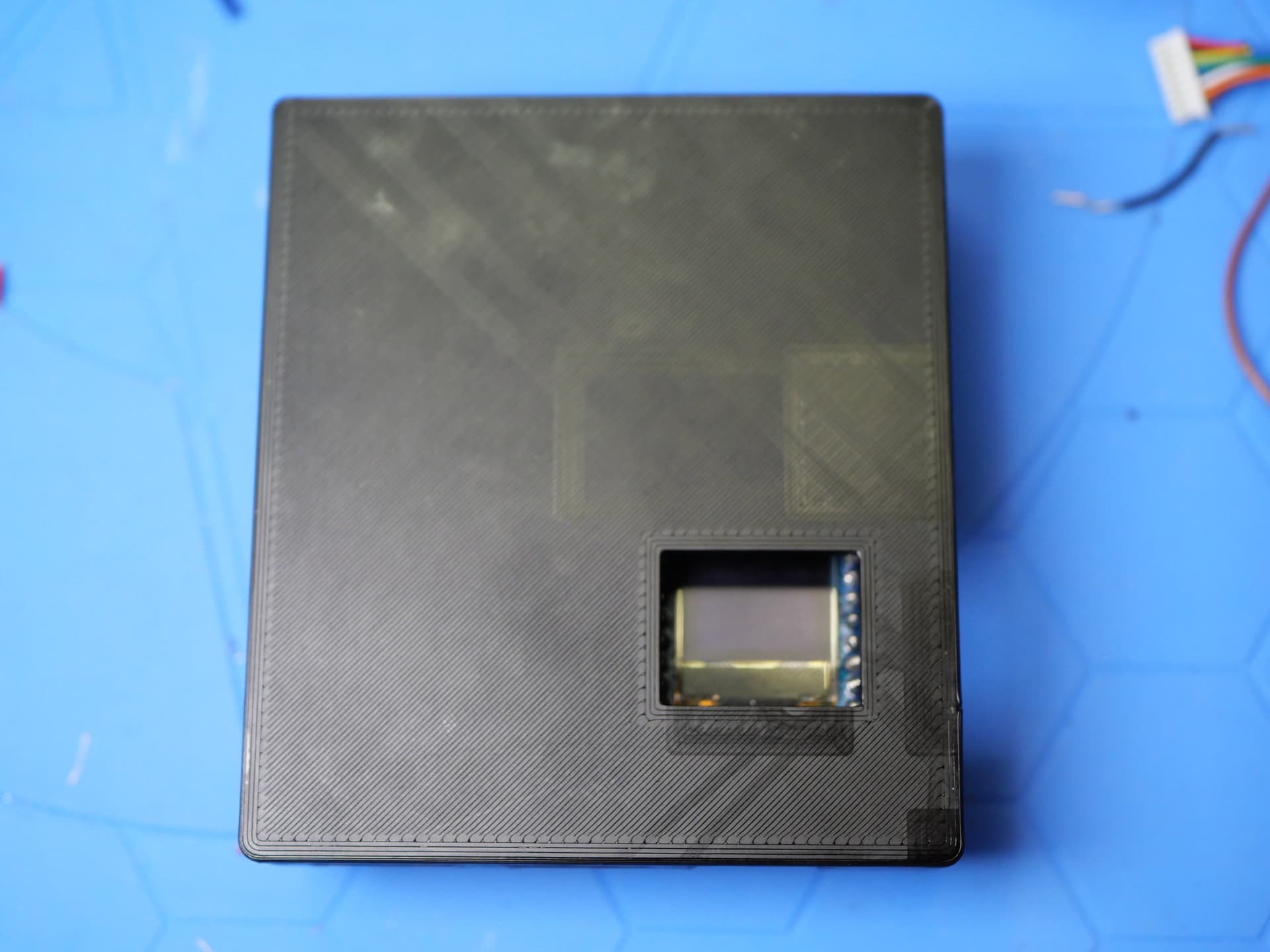
You bet! Here they are!
It looks like the PM2.5 was moved back a bit? I have an older Airgradient DIY in this enclosure and it works fine. I can go grab that perhaps tomorrow if need be (getting late here). You can see the LCD doesn’t line up with the window and that’s because the ridges holding the PM2.5 in place move the board up too high.
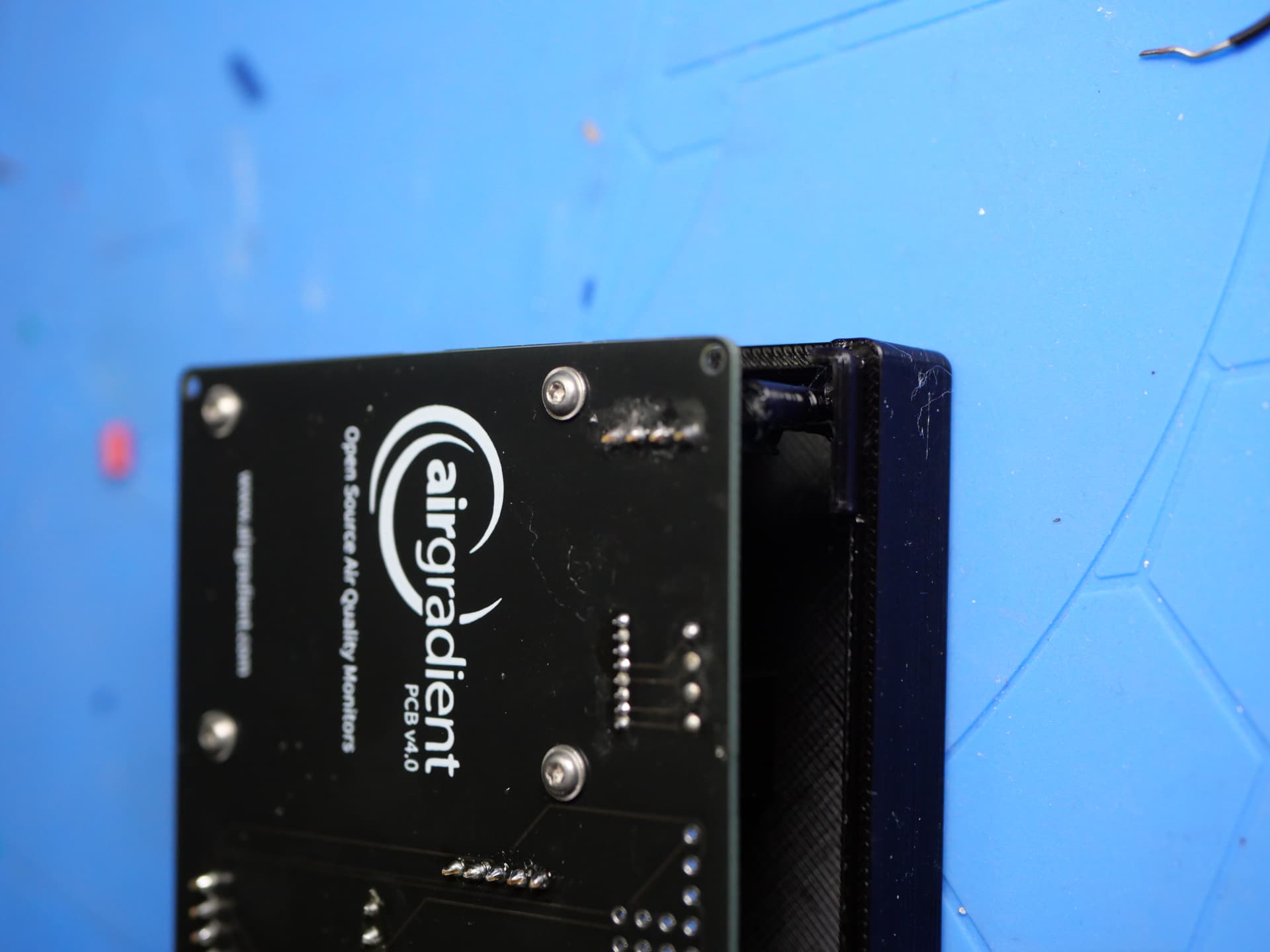
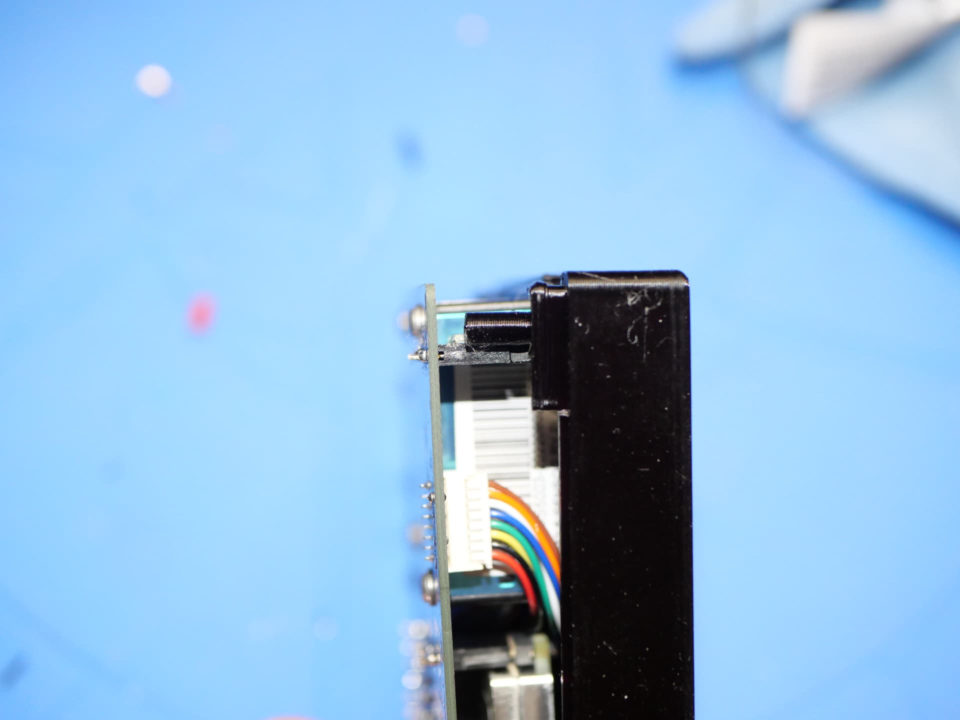
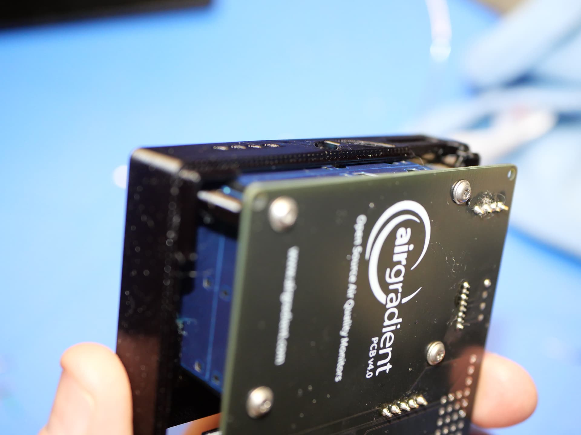
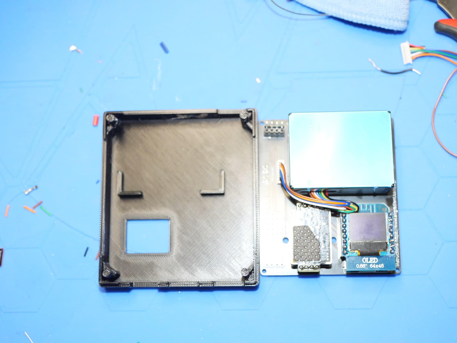
I also encountered the same issue as above. The PM sensor ridges didn’t line up to where the PCB outlines are. The ridges seem to push the sensor tightly into the fan and vent holes of the case, compared to the PCB where there’s still a space at the top.
What I ended up doing was move up the sensor right at the top edge of the PCB, while keeping it lined up, and stuck it with double sided tape. The enclosure was able to close that way, although it was pretty tight.
On another note, with how the guide was worded, I was worried that the OLED module would not fit, but it turns out there’s quite a bit of space before it touches the enclosure. It might be possible to use female headers to attach the controller to make it easier to swap (just like in the DIY Pro), while also pushing the display module up.
Maybe we could also use female headers for the CO2 module, what worries me is if the smaller air gap could affect its readings.
Yes the enclosure needs some adjustments. Unfortunately we are currently pretty stretched ressource wise. Maybe somebody from the community can provide an updated file?
I’d like to confirm that adding female headers to the controller pins is possible, but you’ll need the short ones such as these. With these, you can easily replace the controller on the DIY Basic as well as push the .66 OLED shield closer to the screen cutout.
You can also add female pin headers for the CO2 sensor, the standard height ones will do. However, I had to shave off some of the solder joint for the 5V pin so that the board lays flat.
Has this changed? I can’t find anything in basic.ino regarding flipping the screen (doesn’t matter to me, as I can’t see, but my wife would probably like it if the display weren’t upside down.  )
)
I think the original intent of this case design was to have it flipped around the other way. I’m sure there is a way to flip the display in the Arduino code, but I don’t know how. (Maybe ChatGPT does).
I can flip it in ESPHome pretty easily
I’m a bit late to t he party, but if you want to flip the screen, you need to update the code manually, compile and install using Arduino IDE.
I’m using AirGradient version 2.4.15 on my v2 board. You need to edit DIY_BASIC.
Around line 88, insert the line u8g2.setFlipMode(1); so it looks like below
  u8g2.begin();
  u8g2.setFlipMode(1);
  updateOLED();