>>> Join Us in the Fight Against Air Pollution

AirGradient Forum

Failed to connect to ESP8266: Timed out waiting for packet header

Hello!
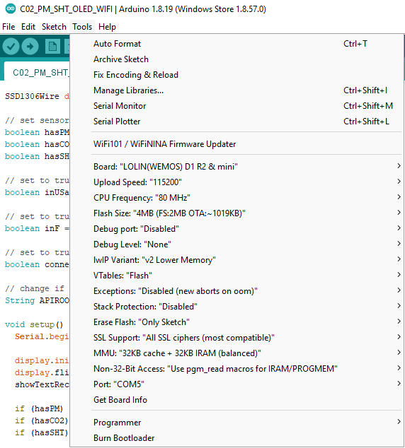
I soldered the sensor according to the instructions (DIY Air Quality Sensor). All solder contacts are good - no breaks (try with tester). Firstly, blink sketch uploaded successfully. Next I tried to upload the “main” sketch (C02_PM_SHT_OLED_WIFI) but my macbook say something about USB power insufficiency and disable it so i moved to PC (Windows 11) but with no luck - when i connect PCB to usb, blue LED permanently lit. Trying to upload sketch - get an error:

Executable segment sizes:
ICACHE : 32768           - flash instruction cache 
IROM   : 355932          - code in flash         (default or ICACHE_FLASH_ATTR) 
IRAM   : 29601   / 32768 - code in IRAM          (IRAM_ATTR, ISRs...) 
DATA   : 1512  )         - initialized variables (global, static) in RAM/HEAP 
RODATA : 2924  ) / 81920 - constants             (global, static) in RAM/HEAP 
BSS    : 26704 )         - zeroed variables      (global, static) in RAM/HEAP 
Sketch uses 389969 bytes (37%) of program storage space. Maximum is 1044464 bytes.
Global variables use 31140 bytes (38%) of dynamic memory, leaving 50780 bytes for local variables. Maximum is 81920 bytes.
esptool.py v3.0
Serial port COM5
Connecting........_____....._____....._____....._____....._____....._____.....____Traceback (most recent call last):
  File "C:\Users\Nikita\Documents\ArduinoData\packages\esp8266\hardware\esp8266\3.0.0/tools/upload.py", line 66, in <module>
    esptool.main(cmdline)
  File "C:/Users/Nikita/Documents/ArduinoData/packages/esp8266/hardware/esp8266/3.0.0/tools/esptool\esptool.py", line 3552, in main
    esp.connect(args.before, args.connect_attempts)
  File "C:/Users/Nikita/Documents/ArduinoData/packages/esp8266/hardware/esp8266/3.0.0/tools/esptool\esptool.py", line 529, in connect
    raise FatalError('Failed to connect to %s: %s' % (self.CHIP_NAME, last_error))
esptool.FatalError: Failed to connect to ESP8266: Timed out waiting for packet header
esptool.FatalError: Failed to connect to ESP8266: Timed out waiting for packet header.

Have no idea how to revive it :frowning:

Already tried to change ports, usb cables, upload speed, clearing flash from esptool for widows, removing screen, disconnecting PMS5003 - with no luck.
Any way to hard reset (with short pins)? Or maybe i need to unsold D1 mini from PCB and deal with it separately?

I appreciate any help and/or suggestions in advance.
Something isn’t right. Try disconnecting the PM2.5 sensor first and see if it’ll take a flash. If it does, then check the wiring for the PM2.5 and try and reconnect it.

The SHT sensor and CO2 sensors can only be mounted one way, and look correct.

You shouldn’t need to desolder the Wemos to flash it. I’d suspect a bad sensor or a bridged solder joint somewhere not shown in your photos. (Connections look clean in your photos.)

I agree with @brianFromNyc . The soldering looks very clean.

Try and flash it without OLED shield and PMS connection but it seems you did that already.

Are you able to flash back the blink code or does it not work anymore at all?

What happen when you press the small reset button on the wemos during “connecting…” ?

What is PM2.5 sensor? Have sensors: senseair, SHT and PMS

Already tried without OLED and PMS - no luck.
Blink wont flash back :frowning:
And nothing happen when pressing reset button, even during connection in sketch only or full reflash.

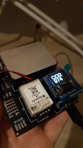
Looking at your 2nd picture, the VIN on the SHT sensor at the underside of the board looks like a cold solder.

Thanks, I’ll go solder again for reliability and recheck if the issue go away :crossed_fingers:
a few moment later… nothing new :frowning:

UPDATE: after PC rebooting i saw this caution:

Over Current Have Been Detected On Your USB Device!!
System will shutdown after 15 seconds to protect your mainboard

How i can diagnose my PCB for overcurrent? - i think this is the key of my issue.

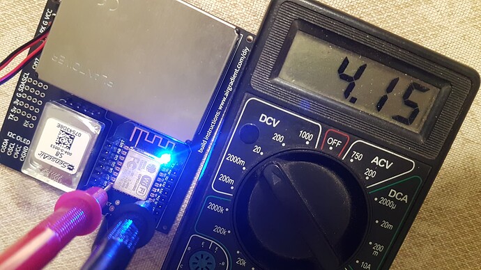
UPDATE #2: on ESP8266 pin 3V3 i have 4.15v - is it ok?

That is not good. The 3,3V should come from the onboard voltage regulator of your Wemos D1.
I would search for a short circuit, which could explain the overcurrent warning. A couple of days I measured also and it was pretty exactly 3.30V.

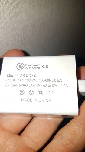
I guess what i did wrong once - i plugged it to the fast charge (i think that can cause overvoltage and burned microcontroller).
Desolded it already and will place order to buy another one or maybe two :slight_smile:
20220117_215505|281x500

What is the best to buy d1 mini or d1 mini v.3.0 / d1 pro 4mb / d1 pro 16mb?

I am building 2 more airgradients and have ordered the V4 version because it has an USB-C connector. Ordered on 13.1 so it will take a couple of more days. If it is the better option, I can not tell yet.

https://nl.aliexpress.com/item/32529101036.html?gatewayAdapt=glo2nld&spm=a2g0o.9042311.0.0.3aab4c4dUGhg1U

Thanks, ttielemans!

I have a news :facepalm:

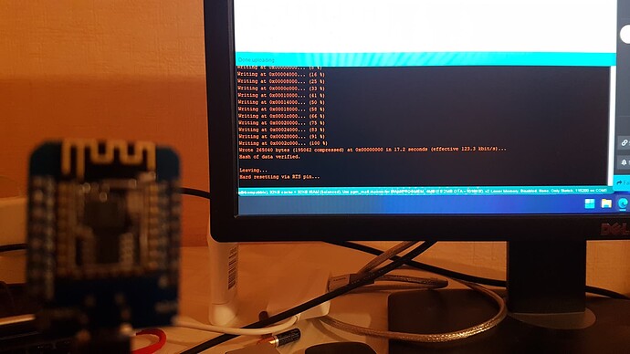
Blink successfully uploaded.

I would be surprised if a fast charger gave it more voltage than it should, as it should only be supplying more amperage if the target device can handle it.

It looks like you are able to flash it now that it has been removed from the board, is that right?

@MallocArray , yes, thats right.
My fast charger could handle up to 12v.

It’s strange, but i uploaded big sketch without any issues.
Soon will solder it again but this time it will be detachable. Will be back.

Guys, thanks to all, problem is gone

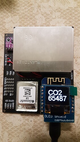
Your CO2 looks way too high. Sensor only delivers a range of 0-10.000.

Do you still have so high values?

@Achim_AirGradient, the values jump
-1
65379
65378
0
65534
65532
65530
65523
-1

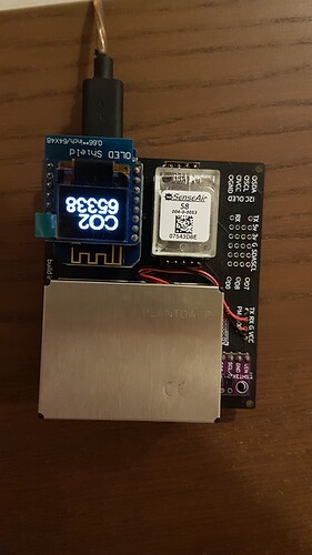
Today it freeze on 65338 :frowning:
Tried to calibrate him by _bCal, after 5 minutes of adequate working the value back to 65338.
if you blow on it with breath, it shows something similar to the truth, but by default his back to this strange value.
What could be wrong?

This is really weird. Never had that issue. Maybe the S8 got damaged through the over voltage?

I’ve done this quest :slight_smile:
Soldered on second PCB, on this time removable.
The clearance between airgradient sensor and pcb is much bigger.
Reflashed, reset bCAL_ and it’s back to life.

Glad that it works now!