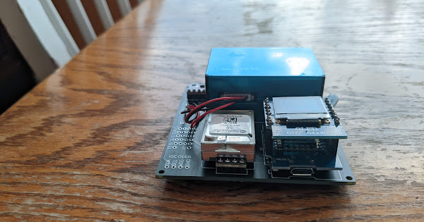
I’ve soldered the DIY basic kit using the guide and Jeff Geerling’s video. Uploading the blink sketch worked, but uploading the DIY_BASIC sketch doesn’t work, version 1.8.19. It uploads, and the light blinks repeatedly, but the OLED doesn’t turn on. I was able to connect to the wifi once, but went back to get the serial number, and have been unable to reconnect to wifi again since, even after re-uploading the sketch.
. Variables and constants in RAM (global, static), used 32240 / 80192 bytes (40%)
║ SEGMENT BYTES DESCRIPTION
╠══ DATA 1512 initialized variables
╠══ RODATA 3656 constants
╚══ BSS 27072 zeroed variables
. Instruction RAM (IRAM_ATTR, ICACHE_RAM_ATTR), used 62675 / 65536 bytes (95%)
║ SEGMENT BYTES DESCRIPTION
╠══ ICACHE 32768 reserved space for flash instruction cache
╚══ IRAM 29907 code in IRAM
. Code in flash (default, ICACHE_FLASH_ATTR), used 340948 / 1048576 bytes (32%)
║ SEGMENT BYTES DESCRIPTION
╚══ IROM 340948 code in flash
esptool.py v3.0
Serial port /dev/cu.usbserial-310
Connecting…
Chip is ESP8266EX
Features: WiFi
Crystal is 26MHz
MAC: 48:55:19:12:02:2b
Uploading stub…
Running stub…
Stub running…
Changing baud rate to 460800
Changed.
Configuring flash size…
Auto-detected Flash size: 4MB
Compressed 380176 bytes to 269710…
Writing at 0x00000000… (5 %)
Writing at 0x00004000… (11 %)
Writing at 0x00008000… (17 %)
Writing at 0x0000c000… (23 %)
Writing at 0x00010000… (29 %)
Writing at 0x00014000… (35 %)
Writing at 0x00018000… (41 %)
Writing at 0x0001c000… (47 %)
Writing at 0x00020000… (52 %)
Writing at 0x00024000… (58 %)
Writing at 0x00028000… (64 %)
Writing at 0x0002c000… (70 %)
Writing at 0x00030000… (76 %)
Writing at 0x00034000… (82 %)
Writing at 0x00038000… (88 %)
Writing at 0x0003c000… (94 %)
Writing at 0x00040000… (100 %)
Wrote 380176 bytes (269710 compressed) at 0x00000000 in 7.0 seconds (effective 434.1 kbit/s)…
Hash of data verified.
Leaving…
Hard resetting via RTS pin…
