Hi all, everything was working great – see video 2021-12-26 First AirGradient DIY Kit Assembled - YouTube
2021-12-26 First AirGradient DIY Kit Assembled - YouTube – and then I went to demonstrate it to my sons before I had put it in the enclosure.
One grabbed it without being grounded (they’re young and I haven’t yet trained then on handling sensitive electronics).
I think there was a static discharge. The display stopped working, so I recompiled and reloaded it with Wi-Fi enabled, and was able to connect it up to the home Wi-Fi, pushing data to AirGradient’s site.
- I’m getting seemingly valid CO2 readings – they’re nearly the same as I got yesterday when the display was working
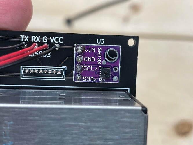
- The temp is incorrectly reporting 32F
- The RH is incorrectly reporting 0
- The PM2.5 appears to be working as it is normally measuring 0…and I was able to get it to spike when I melted some 60/40 rosin solder near the intake
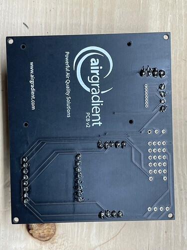
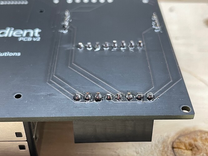
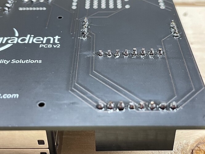
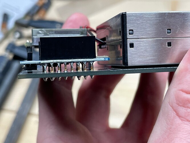
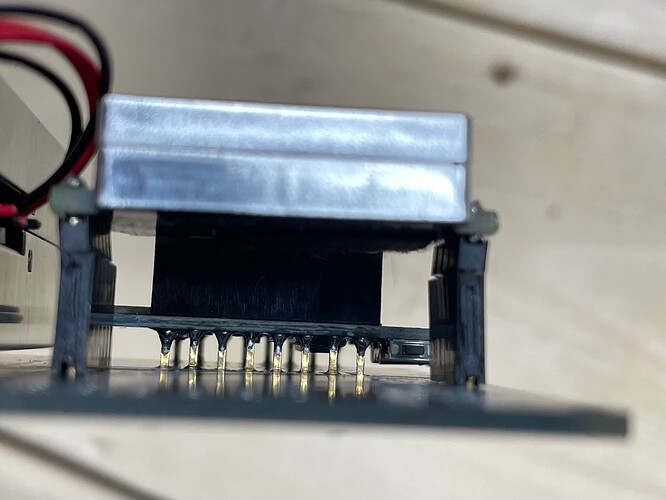
I checked the continuity from top of pin on the display to bottom of pin below the PCB and all of the pins are reporting.
Is there some way I can see if the problem is the display, the I2C controller, …what else? If a semi-conductor is fried, I need to know what to replace.
Are the through-holes on the side of the PCB for testing – the 5x4 grid labeled 5v, 3v, G, SDA, SCL with holes for TX, RX, D7, D8, and D9? If so, how do I use them for testing? I only have a multimeter and a USB console cable…no oscilloscope yet…
Thanks in advance for your help!
