Pro DIY - NOT presoldered
The small lables on PCB like “RST” and “D8” and “GND” do not match with my D1 MIMI component. In the tutorial it says to solder the male pins on the side of the chip with these small labels, but the small labels do not match with labels on the PCB 4.2 board.
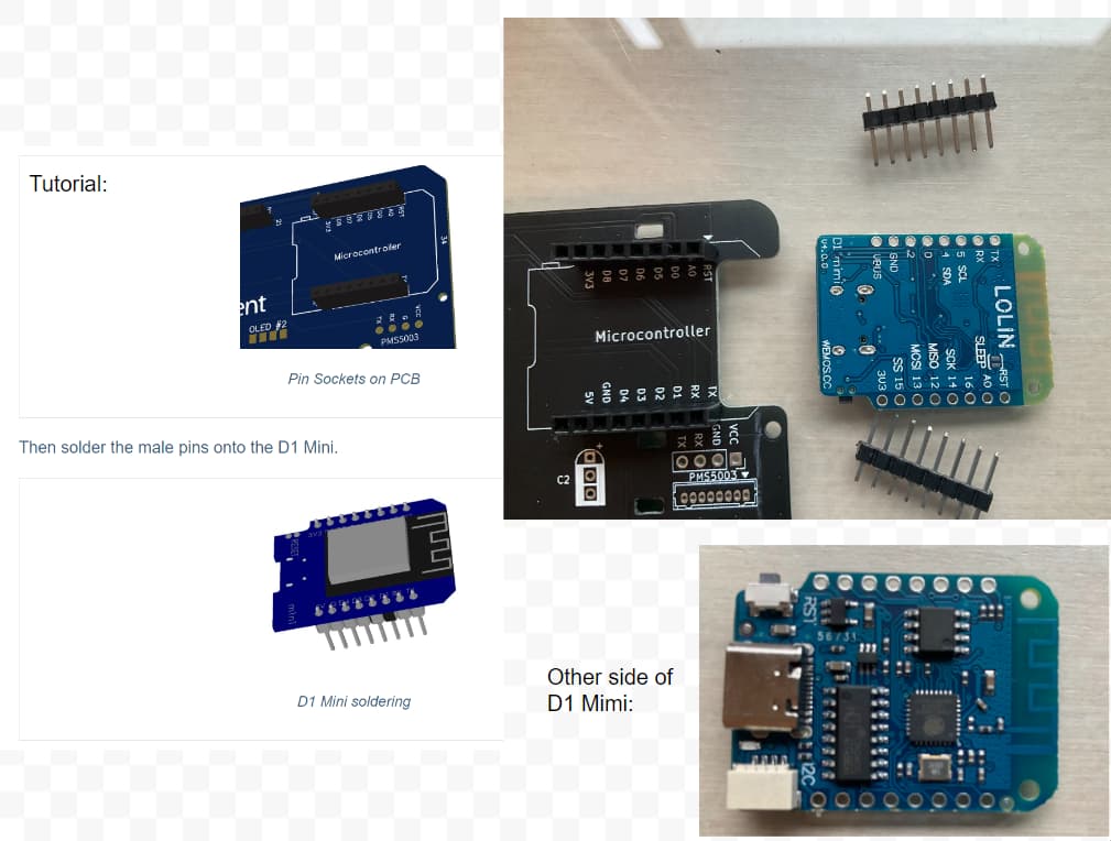
Thank you, so do I solder on the side with or without components? In the top right picture of the image I attatched, note that, for the first 2 holes of the D1 MIMI, TX and RST do not align to RST and TX on the PCB board.
You would flip the board over to the TX/RX pins line up when you set it on top of the socket. That means you would put the short pins through the side without components so they stick up through the side with components and solder on that side.
Then when you insert the pins into the socket, everything should line up.
But double check that it makes sense to you before believing some rando on the internet. 
1 Like