I’ve just finished building up the PRO kit v3 and I thought I would give some feedback on the build instructions. Before I do I have to say that all seems to be working fine so far. I was able to solder the JST connector and USB port with a standard soldering iron and no magnifying glass. I have to say though that before attaching anything on them I did a continuity test with a multimeter making sure there was no short considering how tight and small the pins are. Ok so here are my comments for improving the instructions:
-
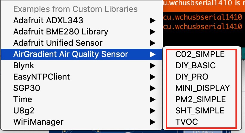
When manual flashing the D1 Mini there is no “PM OLED” code. I think I mentioned this in a previous thread but it hasn’t been updated so far. This is what we see:
Having the DIY Pro kit I took the code with the same name assuming it’s the code needed. -
There are 3 sets of different screws in the kit. There is no mention which is for what. I had to figure it out and I think it’s ok but I suppose if you use the longer screws specially on the PM2.5 sensor it could damage the sensor case/thread. So it might be a good idea to mention which screws are for what. Also the screws to fix in place the enclosure are rather difficult to screw. I really had to use some force. The ones I used are the longer ones which I assume are the correct ones.
In summary: the smaller ones are meant to attach the board to the case. While the black ones are for the PM2.5 sensor and the longer ones for the case. Correct me if I’m wrong! -
There are 2 resistors in the kit which there is no mention about in the build instructions. I didn’t solder them to the board but I see there are two slots available on the board for them. So what to do here?
-
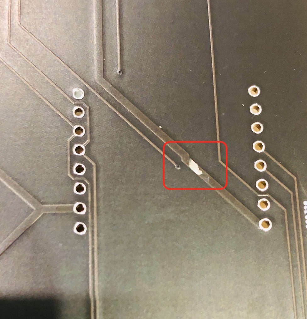
This is unrelated to the build instructions but how the kit was packed. The positive first. I appreciated that most of the components were packed in recyclable paper. Kudos for that. Not often we see this. Now the negative. The usb cable being inside the case in contact with the board ended up scratching a trace and leaving it exposed. Fortunately the trace doesn’t seem to have been severed. I’ll just add some nail polish to cover it and prevent it from oxidising. So it might be worth separating the usb cable from the board to prevent this type of damage.
-
For those who wish to use Airgradient Dashboard there should be a link at the end of the build instructions pointing them to the right direction. At first I was not sure what to do and started looking around until I saw the “Dashboard” at the very bottom of the page which I clicked. But then when the page opened we are only greated with a Sign in option and no option to create an account. So I was back to square one. I finally found how to and it was a bit convoluted. I had to go to the Support page, scroll down, click the AirGradient Manual Access link, scroll down then click the AirGradient Dashboard link at the bottom of the page. There, I was able to create an account, but then I was asked for a serial number which at not point in the build instruction is this mentioned. So after a bit of guessing I looked at the serial monitor and noted this “airgradient:xxxxxx” which I assumed was the serial number. Finally worked.
-
Final comment on the dashboard. I think some improvement could be done but without going into too much detail, there is something strange. I can’t remove the “Outdoors locations”. I have no use for that yet it’s there can’t be removed.
That’s all for me.
edit: added details.