Battery backup questions for v1 of pro kit

Hi
I’ve just got around to building the pro kit that I received early summer. I think I have the version from the first wave.

I was curious if there was more information on the battery backup module and whether I should be powering that module or the D1? Thanks

The battery pack you can put on the slot called D1 Mini Shield. Then connect a LiPo battery to the shield and plug the power to the shield. This will automatically charge the battery if needed and switch to the battery if you unplug the power.

I can confirm this works. If you are more daring you could try to add a voltage divider(with resistors) to connect the positive connector of the battery to the adc pin(A0) on the charge module. Bring the voltage from max 4.2v down to 1v so you can measure it and roughly estimate how charged your battery is.

Thanks! Might try that

Thanks so much. I’ve ordered a battery

Does anyone know the connector type for the battery? The one mine came with was too small.

I soldered the battery in and it powered everything but the temp/hum sensor no longer was reading a value and the tvoc value was sky high so I unsoldered it

My v1 pro kit came with a ph connector and leads so I only needed it to solder to the battery itself. Maybe you can cut the connector of the battery and just replace it?
The connector on the battery shield is PH2-2.0MM
My battery came from an e-cig, those cells contain 400mAh and runs for over an hour. Enough to calibrate co2 outside. For reference an image of the modification.


Thank you so much.

My kit also came with that connector. I simply forgot about it!

I noticed that the connector leads polarity is reversed compared to the board so I had to take care of this.
Something for Achim to look into maybe.

Those voltage drop resistors…I guess you read the voltage from that board with additional code?

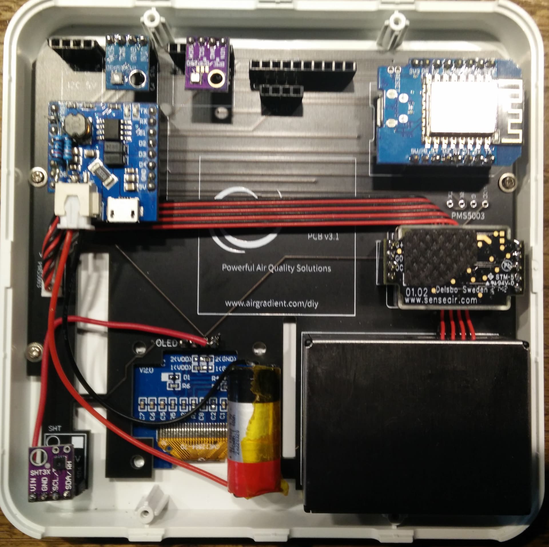
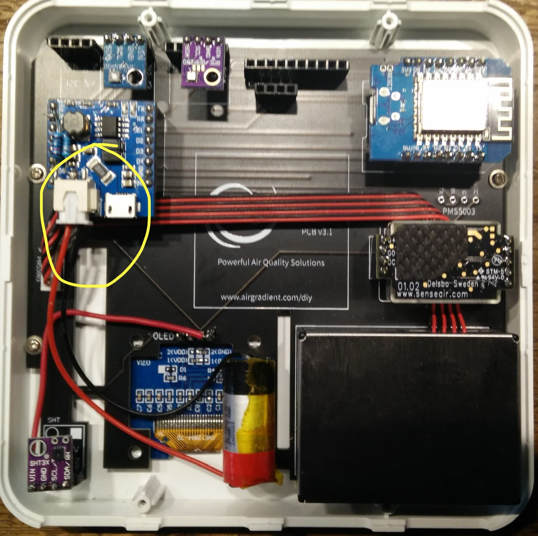
Indeed, the leads were reversed. But simply swap them for reference. I guess the person assembled this doesnt have a clue.

Yes I read the adc with different code. Let’s say a different platform because I have it ported to esphome. For example:

substitutions:
  devicename: "airgradient"
  upper_devicename: "Airgradient"
  voltage_divider: "4.27238" #Battery input 119k resistor
  battery_warning_voltage: "3.6"
  battery_low_voltage: "3.2"
  - platform: adc
    pin: A0
    name: "${upper_devicename} Battery Voltage"
    id: batv
    filters:
      - multiply: ${voltage_divider}
      - sliding_window_moving_average:
          window_size: 10
          send_every: 10
    on_value:
      - sensor.template.publish:
          id: battery_percentage
          state: !lambda |-
            int batper = (x - ${battery_low_voltage}) / (4.2 - ${battery_low_voltage}) * 100;
            if(batper > 100) { batper = 100; }
            if(batper < 0) { batper = 0; }
            return batper;
    disabled_by_default: true
    update_interval: 1s
    entity_category: diagnostic
  - platform: template
    name: "${upper_devicename} Battery Percentage"
    id: battery_percentage
    device_class: battery
    accuracy_decimals: 0
    unit_of_measurement: "%"
    entity_category: diagnostic

Just want to confirm. You talk about the battery connector with the two wires for the battery shield?

The yellow circled connector. The polarity of the wires on the connector was reversed from what is required for that board

Thanks. We will keep an eye on this next time we buy this cable.