>>> Join Us in the Fight Against Air Pollution

AirGradient Forum

Airgradient pro reflashed with ESPhome: sometimes partially freeze and need power cycle

Hi all,
I reflashed my Airgradient PRO with ESPhome in order to easily manage and integrate from HomeAssistant.
Sometimes it happened that SHT31 and SGP41 stops reporting data and the OLED display freeze.

here the logs i collected

below my configuration file

anyboday has some idea?

thanks
bye
Marco

# Airgradient Pro presoldered edition
# D1 mini v4.0.0 with usb c port
substitutions:
  devicename: "airgradient-pro"
  upper_devicename: "Airgradient Pro"

esphome:
  name: "${devicename}"
  # Automatically add the mac address to the name
  # so you can use a single firmware for all devices
  # name_add_mac_suffix: true
  platform: ESP8266
  board: d1_mini

# Enable logging
logger:

# Enable Home Assistant API
api:
  encryption:
    key: "xxxxxxxxxxxxxxxxxxxxxxx="

ota:
  password: "xxxxxxxxxxxxxxxxxxxxxxxx"

# dashboard_import:
# package_import_url: github://esphome/esphome-project-template/project-template-esp32.yaml@v6
  # package_import_url: github://ajfriesen/ESPHome-AirGradient/main/air-gradient.yaml


wifi:
  networks:
  - ssid: !secret wifi_ssid
    password: !secret wifi_password
  reboot_timeout: 15min

  # Enable fallback hotspot (captive portal) in case wifi connection fails
  ap:
    ssid: ${upper_devicename} Fallback Hotspot
    password: "xxxxxxxxxxxxxxxxx"

switch:
  - platform: safe_mode
    name: "Flash Mode (Safe Mode)"
  - platform: restart
    name: "Airgradient pro restart"

captive_portal:

i2c:
  sda: D2
  scl: D1

font:
#  - file: "font/t0-16.bdf"
# - file: "font/monofont.ttf"
  - file: "font/LiberationSans-Regular.ttf"
    id: opensans
    size: 24

display:
  - platform: ssd1306_i2c
    id: oled
    address: 0x3c
    rotation: 180°
    model: "SH1106 128x64"
    pages:
#      - id: page1
#        lambda: |-
#          it.printf(0, 0, id(opensans), "CO2: %.0f ppm", id(co2).state);
#          it.printf(0, 20, id(opensans), "PM25: %.0f, VOC: %.0f", id(pm25).state, id(voc).state);
#          it.printf(0, 40, id(opensans), "T: %.1f°C, H: %.0f %%", id(temp).state, id(humidity).state);
      - id: display_temp_hum
        lambda: |-
          it.printf(0, 0, id(opensans), "Temp: %.1f °C", id(temp).state);
          it.printf(0, 24, id(opensans), "Hum: %.0f%%", id(humidity).state);
      - id: display_pm2
        lambda: |-
          it.print(0, 0, id(opensans), "PM2.5");
          it.printf(0, 24, id(opensans), "%.0f ug/m3",id(pm25).state);
      - id: display_co2
        lambda: |-
          it.print(0, 0, id(opensans), "CO2");
          it.printf(0, 24, id(opensans), "%.0f ppm",id(co2).state);
      # - id: display_eco2
      #   lambda: |-
      #     it.print(0, 0, id(opensans), "eCO2");
      #     it.printf(64, 24, id(opensans), TextAlign::TOP_RIGHT, "%.0f",id(eco2).state);
      - id: display_tvoc
        lambda: |-
          it.print(0, 0, id(opensans), "VOC");
          it.printf(64, 24, id(opensans), TextAlign::TOP_RIGHT, "%.0f",id(voc).state);

# Maybe add a page later

interval:
  - interval: 5s
    then:
      - display.page.show_next: oled
      - component.update: oled

uart:
  - rx_pin: D5
    tx_pin: D6
    baud_rate: 9600
    id: uart1
    
  - rx_pin: D4
    tx_pin: D3
    baud_rate: 9600
    id: uart2

sensor:
  - platform: sht3xd
    temperature:
      id: temp
      name: ${upper_devicename} Temperature
    humidity:
      id: humidity
      name: ${upper_devicename} Humidity
    address: 0x44
    update_interval: 30s
    
  - platform: pmsx003
    type: PMSX003
    uart_id: uart1
    update_interval: 60000ms
    pm_2_5:
      id: pm25
      name: "${upper_devicename} Particulate Matter <2.5µm Concentration"
    pm_10_0:
      id: pm100
      name: "${upper_devicename} Particulate Matter <10.0µm Concentration"
#    formaldehyde:
#      id: hcho
#      name: "Formaldehyde (HCHO) concentration in µg per cubic meter"
      
  - platform: senseair
    uart_id: uart2
    co2:
      id: co2
      name: "${upper_devicename} SenseAir CO2 Value"
    update_interval: 60s

  - platform: sgp4x
  # https://esphome.io/components/sensor/sgp4x.html
    nox:
      name: "${upper_devicename} NOx index"
      id: nox
      accuracy_decimals: 1
    voc:
      name: "${upper_devicename} VOC index"
      id: voc
      accuracy_decimals: 1
    update_interval: 60s
    compensation:
      humidity_source: humidity
      temperature_source: temp


  - platform: wifi_signal
    name: "WiFi Signal"
    update_interval: 30s
    id: airgradient_wifi_signal
This sounds like your I2C bus is hanging and doesn’t recover. The oled is also on this bus and is sensitive to these issues. This can have multiple causes but check if everything is connected as it should be. Check your solder joints and maybe reflow it to be sure.

Then your bus should be pulled up the right amount with the pullup resistors. When the sensors are operating they need to be able to sink down the bus so a too strong pullup causes weak singals. On some sensors there are pullups and the total value depends on your bus speed and amount of sensors. The easy way to test is to change your bus speed and see if issues go away. Mine is at 100khz. Otherwise you have to change/remove pullup resistors.
EDIT: Removing a sensor achieves the same for testing purposes.

Happy to hear what settings/modifications work for you.

The I2C bus defaults to 50kHz in ESPHome. Since I have the same issue, I’m going to test 100kHz.

First step is to verify pull-ups. Using a DMM, measure resistance between:

  • SCL <-> SDA
  • SCL <-> 5.0V
  • SDA <-> 5.0V
  • SCL <-> 3.3V
  • SDA <-> 3.3V

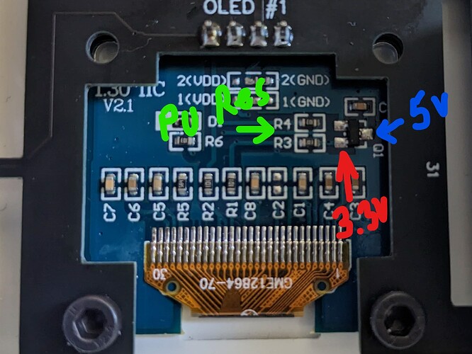
On mine, there is an LDO on the OLED board that drops 5V → 3.3V and there are 10K pull-ups to that rail.

Hi, Thank you for your feedback.
I was also thinking about i2c hang.
I suppose it is well soldered since I bought the pre soldered version since I was not so sure about my soldering skills…

I just tried add
frequency: 100kHz

I’m going to monitor it for a week to check if it happen again.

I can try to measure resistance as per @ken830 suggestion, but ink not sure where I can find SDA and SCL. Which are expected values?

Maybe @Achim_AirGradient that soldered it, can add some hint about this topic?

Thanks everybody for the support

Marco

The 100kHz setting seems really promising. After a day, I’ve seen no issues with an AG 1st gen and an AG Pro running the latest version of ESPHome. I’ll keep monitoring for issues though.

@chase.tb if it continues to work please share some details how to do the change to 100hz for others. Thanks.

I’ll test 100kHz as well after I’m done testing using an older version of PlatformIO

I²C Bus — ESPHome
Link above is all documentation for ESPHome and i2c, including the frequency parameter, which defaults to 50kHz, but can be modified like:

i2c:
  sda: D2
  scl: D1
  frequency: 100kHz

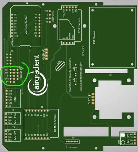
Slowing down the I2C bus can hide or overcome some fundamental problems with the bus. Regardless, you should check the pull-up resistors. SCL and SDA are clearly marked on the Pro Kit PCBAs. All instances of them are tied together, so it doesn’t matter which point you measure from.

Assuming a single 10Kohm pull-up resistors on each SCL and SDA, measuring between SCL and SDA should yield a reading of 20Kohm. Confirming that measurement first is a good first step. Then, you can measure between SCL or SDA and the voltage rail to figure out which rail it’s pulled-up to: 5V (from the D1 mini), 3.3V (from the D1 mini), or 3.3V (from the OLED PCB).

But it is strange to me that 100kHz would work better than 50kHz unless there is a minimum SCL frequency, but the SH1106, SGP41, and SHT3x all specify DC (0 Hz) as the minimum clock frequency as is expected of all I2C devices. Perhaps it’s the inability for the parts to sink enough current to pull-down the bus low enough for long enough for every device to properly see a LOW. Arduino’s Wire object defaults to 100kHz.

When debugging the i2c bus speed I found out that the oled is updated too slow (>1 sec) when busspeed is lower than 50khz. I update at 1 sec interval. You can literally see the data drawn on the screen. Fun effect though.

Also low bus speeds keeps the D1 mini busy while updating the oled so it loses wifi connection. I would recommend using 100khz and all components should work at that speed but esphome comes default at 50khz.

Day 2 of running 100kHz. No I2C errors in the logs. The displays are staying up-to-date and the sensors are all reporting values. There were a couple of UART errors with the SenseAir (see below) but it seems to have recovered without a reboot or hard hard reset.

[12:09:49][E][uart:015]: Reading from UART timed out at byte 6!
[12:09:49][W][senseair:024]: Reading data from SenseAir failed!

I think I’ve seen that same error and probably has something to do with how esphome handles it. If data is still coming in I wouldn’t worry too much about it.

The AG 1 is still going strong without any I2C errors but the AG Pro display has frozen again. Here are the relevant errors in the logs:

[15:53:02][I][i2c.arduino:068]: Results from i2c bus scan:
[15:53:02][E][i2c.arduino:076]: Unknown error at address 0x08

[15:53:03][C][sht3xd:029]: SHT3xD:
[15:53:03][C][sht3xd:030]:   Address: 0x44
[15:53:03][E][sht3xd:032]: Communication with SHT3xD failed!
[15:53:03][C][sht3xd:034]:   Update Interval: 90.0s

[15:53:04][W][sgp30:237]: Unknown setup error!

[15:53:04][C][ssd1306_i2c:023]: I2C SSD1306
[15:53:04][C][ssd1306_i2c:023]:   Rotations: 0 °
[15:53:04][C][ssd1306_i2c:023]:   Dimensions: 128px x 64px
[15:53:04][C][ssd1306_i2c:024]:   Address: 0x3C
[15:53:04][C][ssd1306_i2c:025]:   Model: SH1106 128x64
[15:53:04][C][ssd1306_i2c:027]:   External VCC: NO
[15:53:04][C][ssd1306_i2c:028]:   Flip X: YES
[15:53:04][C][ssd1306_i2c:029]:   Flip Y: YES
[15:53:04][C][ssd1306_i2c:030]:   Offset X: 0
[15:53:04][C][ssd1306_i2c:031]:   Offset Y: 0
[15:53:04][C][ssd1306_i2c:032]:   Inverted Color: NO
[15:53:04][C][ssd1306_i2c:033]:   Update Interval: 1.0s
[15:53:04][E][ssd1306_i2c:036]: Communication with SSD1306 failed!

Is that at the initial boot or only after it has been running for some time and you see this when the display freezes?

It had been running for about 2 days. If I power cycle it, nothing appears immediately wrong but it’s just a matter of time

If I were you, I wouldn’t waste any time debugging or testing anything unless I was 100% sure there isn’t a weird pull-up situation on your I2C bus. I didn’t see you say that you’ve verified that yet. My AP Pro kit had pull-ups on the SHT board which would conflict with the pull-ups on the OLED board.

This information is only gathered while booting. When requesting the logs it will put out this information but it’s not at that moment generated. If esphome determines that a sensor doesnt work it will not use it. I guess something isn’t right with that i2c bus because of that error on address 0x08 which isn’t a normal device address. Maybe its an indication why SGP and SSD1306 isn’t setup. Are they even connected or working at all?

Please determine if every sensor is working after a restart. And that the freeze happens after that. Otherwise your issue should be moved to a new/other topic.

In the DIY instructions for the Pro, it mentions that “removing the pull-up resistors on any of the modules will help.” Then gives an example of removing two resistors on the SHT board. I removed those and then the SHT module doesn’t work anymore. Put them back and it works again.

I’m a novice when it comes to I2C but I do have a digital multimeter. With it set to 20k ohms, here are the measurements:

  • SCL <-> SDA: 9.83
  • SCL <-> 5.0V: 9.49
  • SDA <-> 5.0V: 18.40
  • SCL <-> 3.3V: 7.20
  • SDA <-> 3.3V: 7.38

Yes, every sensor works on boot. Confirmed by watching the Serial Monitor in the Arduino IDE with a USB-C cable plugged directly into the D1 Mini v4

Assuming you have the V3.3 PCB like me: I haven’t removed the resistors on my SHT board yet, so I don’t know if I would expect it to work either on the 5V rail with 3.3V pull-ups.

Sorry. I sometimes assume some un-realistic level of electronics knowledge. I realize I may have been too vague. First off, what PCB version do you have? And let’s start clean with the measurements:

  1. Pull off everything you can. I assume that will be just the OLED on the PCB and nothing else. measure resistance between SCL and SDA on the PCB.
  2. Measure resistance between SCL and 3.3V (AirGradient PCB)
  3. Measure resistance between SDA and 3.3V (AirGradient PCB)
  4. Measure resistance between SCL and 5V
  5. Measure resistance between SDA and 5V

Now look at the OLED board and measure resistance again, but this time to the pin I’ve marked “3.3V” in the picture below:

  1. Measure resistance between SCL and 3.3V (OLED PCB)
  2. Measure resistance between SDA and 3.3V (OLED PCB)

Now plug in your I2C devices (SHT and SGP) and take the following measurements:

  1. Measure resistance between SCL and SDA
  2. Measure resistance between SCL and 3.3V (AirGradient PCB)
  3. Measure resistance between SDA and 3.3V (AirGradient PCB)
  4. Measure resistance between SCL and 5V
  5. Measure resistance between SDA and 5V