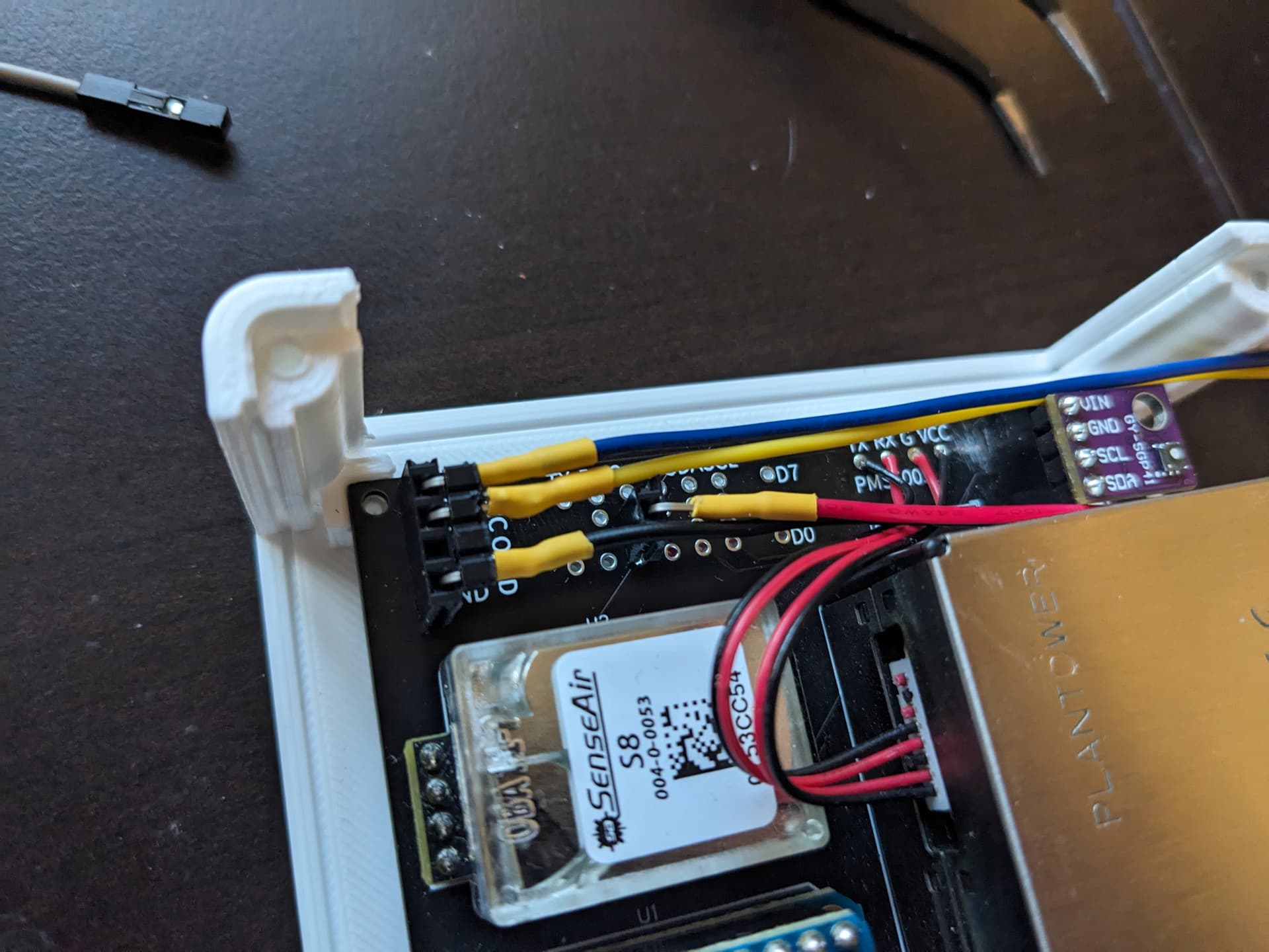
So I began going down the rabbit hole of adding an SGP41 sensor to my existing AGv2 board. However, when I first added it, I kept having I2C issues. The bus would become unresponsive and stopped entirely. After purchasing an oscilloscope and spending time learning I2C, it turned out to be a mix of too many pull-up resistors – SDA/SCL pull-ups on both the LCD and SGP41 board, as well as a pull-up on SCL on the SHT30 board. However, even after fixing that by cutting the leads on the SGP41 board, I was still having issues.
It turned out that the SHT30 leads had a 5v pull-up, and the LCD display had a 3v pull-up. Apparently they have enough tolerance to work together, which was strange. However, when adding the SGP41, things did not work.
I have spent so much time on this, but thought I’d share it. I could have just purchased a new “pro” version, but I didn’t want to have to de-solder my PMS and S8 sensors.
These are the mods I made to get a fully working v2 PCB with an Aliexpress sourced SGP41 and SHT30:
- Installed SGP41 sensor in the U3/Temp sensor port
- Cutting 5v trace to the U3/Temp sensor port and running 3v to VCC (on back of board)
- Installing female headers to secondary I2C OLED port (I couldn’t cut this trace though, since there were leads to other parts of the board).
- Installed a single female header to 3v
- Running wires from new female pin headers to SHT30 as an external sensor
My temperature should now be more accurate, since I will be running it outside of my 3d printed case.
Hopefully others will also find this useful 