Airgradient One v9 configuration for Tasmota

Hello,

Trying to get the Airgradient One v9 working with Tasmota. I have flashed it with Tasmota 13.4.0.1 (tasmota32 C3) and connected it to wifi.

I’m using this diagram: https://www.airgradient.com/images/pages/instructions/v9/v9_schematics.webp from the documentation: The AirGradient ONE Air Quality Sensor (Presoldered-Version, PCB Version 9)

It says that the GPIO pins are:
GPIO-06: SCL
GPIO-07: SDA

Here is the Tasmota logs upon bootup:

00:00:00.001 HDW: ESP32-C3 v0.4 
00:00:00.014 UFS: FlashFS mounted with 2224 kB free
00:00:00.023 CFG: Loaded from File, Count 26
00:00:00.029 QPC: Count 1
00:00:00.032 I2C: Bus1 using GPIO06(SCL) and GPIO07(SDA)
00:00:00.036 TFS: File 'mcp23x.dat' not found
00:00:00.074 BRY: Berry initialized, RAM used 4382 bytes
00:00:00.085 Project tasmota - AirGradient Pro v9 Version 13.4.0.1(tasmota32_2M)-2_0_14(2024-02-16T19:32:03)
00:00:01.001 WIF: Connecting to AP1 XXXXX Channel 3 BSSId XX:XX:XX:XX:XX:XX in mode 11n as tasmota-XXXXXX-XXXX...
00:00:03.503 WIF: Connected

When I attempt to run i2cscan, I get:

08:14:44.503 CMD: i2cscan
08:14:44.521 RSL: RESULT = {"I2CScan":"Error"}

I haven’t yet tried to connect up the other sensors, trying to get I2C working first.

Has anyone had any luck?

Okay, it appears that build of Tasmota does not have sensors built in. I have compiled Tasmota with these sensors enabled and it seems to be working. I’m currently figuring out how to control the OLED screen and the RGBLEDs. Usually the screen just works with:

DisplayModel 2
DisplayMode 0
DisplayText hi

From: Displays - Tasmota

But it doesn’t seem to right now.

The template I’m using is:

{"NAME":"AirGradient Pro v9","GPIO":[1632,1600,283,1,1,1,608,640,0,0,1376,0,0,0,0,0,0,0,0,0,1696,1664],"FLAG":0,"BASE":1}

Okay! Got most of it working.

The OLED screen currently displays garbage after turning it on from the Toggle button on the main menu, but will briefly flash text on it when issuing the DisplayText command. I have all the sensors working, and I think I’ve got the WatchDog circuit under control on GPIO-02 to stop it from rebooting the device every few minutes.

Here’s my template:

{"NAME":"AirGradient Pro v9","GPIO":[1632,1600,283,1,1,1,608,640,0,0,1376,0,0,0,0,0,0,0,0,0,1696,1664],"FLAG":0,"BASE":1}

I’ve compiled Tasmota ESP32 C3 with:

#define USE_SHT
#define USE_BMP
#define USE_BME
#define USE_ADS1115
#define USE_SHT3X
#define USE_SENSEAIR
#define USE_PMS5003
#define USE_DISPLAY
#define USE_SGP41
#define WS2812_LEDS 11

In user_config_override.h and can control the LEDs over MQTT or just with the LEDx RRGGBB command.

I would upload the firmware bin file here, but the forum is preventing me, so you’ll have to compile yourself.

Solved!

The forum won’t let me upload the firmware bin file, and honestly, you shouldn’t trust it from some random person on the internet. Maybe the person who runs templates.blakadder.com can build and upload this custom version of the binary with these instructions.

Here’s how I did it:

You will first need to compile Tasmota with the following in your tasmota/user_config_override.h file:

// These are necessary:
#define USE_SHT
#define USE_SHT3X
#define USE_SENSEAIR
#define USE_PMS5003
#define USE_DISPLAY
#define USE_DISPLAY_SH1106
#define USE_SGP41
#define WS2812_LEDS 11

#ifndef USE_RULES
#define USE_RULES
#endif

// The rest below are optional
#define USE_BMP
#define USE_BME
#define USE_ADS1115

#ifdef USER_TEMPLATE
#undef USER_TEMPLATE
#endif
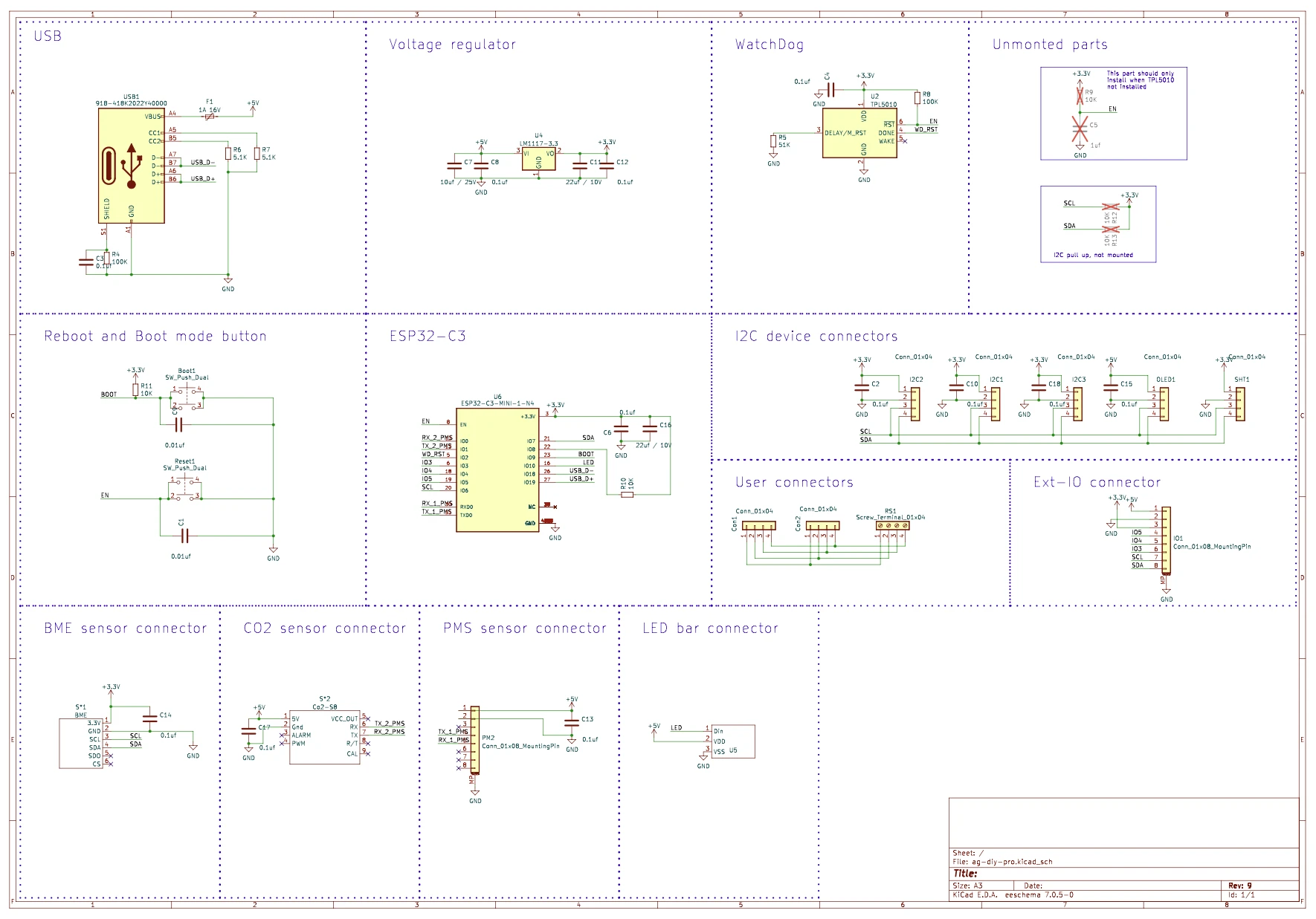
#define USER_TEMPLATE "{\"NAME\":\"AirGradient Pro v9\",\"GPIO\":[1632,1600,224,1,1,1,608,640,0,0,1376,0,0,0,0,0,0,0,0,0,1696,1664],\"FLAG\":0,\"BASE\":1}"

// This runs the first time the firmware is installed.
// You can remove 'Dimmer2 40;' and anything else __AFTER__ 'DisplayAddress1 60;'
// This is just to show that the firmware is installed and working.
#define USER_BACKLOG "Module 0; DisplayMode 0; DisplayModel 7; PulseTime1 1 Power2 On; Power3 On; Rule1 On; Rule2 On; Power1 On; DisplayAddress1 60; Dimmer2 40; Color2 00ff55; Led1 222222"

// Watchdog keep alive
#ifdef USER_RULE1
#undef USER_RULE1
#endif
#ifndef USER_RULE1
#define USER_RULE1 "On Time#Minute DO Power1 On ENDON"
#endif

// Display
#ifdef USER_RULE2
#undef USER_RULE2
#endif
#define USER_RULE2 "On SHT4X#Temperature do DisplayText [s1l1c1]T: %value%C endon on SHT4X#Humidity do DisplayText [s1l1c11]H: %value%% endon on S8#CarbonDioxide do DisplayText [s1l2c1]CO2: %value% ppm endon on PMS5003#PM2.5 do DisplayText [s1l3c1]PM2.5: %value% endon on PMS5003#PM10 do DisplayText [s1l3c11]PM10: %value% endon on PMS5003#PB0.3 do DisplayText [s1l4c1]PB.3: %value% endon on SHT4X#Temperature do DisplayText [s1l5c1]%timestamp% endon on tele-DisplayText [s1l6c1] endon"

#ifndef DISPLAY_MODEL
#define DISPLAY_MODEL 7
#endif

I tried to compile with the template, rules and display mode set, but not sure if it’s working. If it’s not, no big deal, you can apply these settings manually in the Tasmota console as explained below. The most important thing is compiling with the sensors and display code in the firmware.

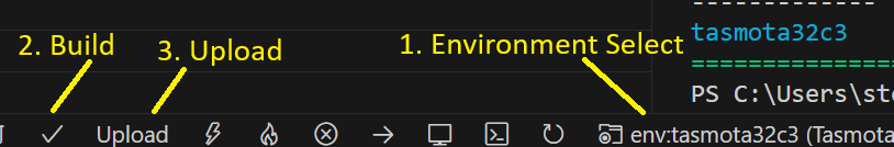
You will also need to comment out tasmota and uncomment tasmota32 in the platformio_override.ini file.

Select the tasmota32c3 environment if using vscode:

Build and upload.

Manual settings:

Use template:

{"NAME":"AirGradient Pro v9","GPIO":[1632,1600,224,1,1,1,608,640,0,0,1376,0,0,0,0,0,0,0,0,0,1696,1664],"FLAG":0,"BASE":1}

Rule 1 (In console) for Watchdog pulse (Relay1, GPIO-02). Setting this will prevent the AirGradient from rebooting every 30~ minutes:

Rule1 ON Time#Minute DO Power1 On ENDON
Rule1 On

Rule2 (In Console) for display:

Rule2 on SHT4X#Temperature do DisplayText [s1l1c1]T: %value%C endon on SHT4X#Humidity do DisplayText [s1l1c11]H: %value%% endon on S8#CarbonDioxide do DisplayText [s1l2c1]CO2: %value% ppm endon on PMS5003#PM2.5 do DisplayText [s1l3c1]PM2.5: %value% endon on PMS5003#PM10 do DisplayText [s1l3c11]PM10: %value% endon on PMS5003#PB0.3 do DisplayText [s1l4c1]PB.3: %value% endon on SHT4X#Temperature do DisplayText [s1l5c1]%timestamp% endon on tele-DisplayText [s1l6c1] endon
Rule2 On

If using an BME680, you can set Rule2 to:

Rule2 on BME680#Temperature do DisplayText [s1l1c1]T: %value%C endon  on BME680#Humidity do DisplayText [s1l1c11]H: %value%% endon  on S8#CarbonDioxide do DisplayText [s1l2c1]CO2: %value% ppm endon  on PMS5003#PM2.5 do DisplayText [s1l3c1]PM2.5: %value% endon  on PMS5003#PM10 do DisplayText [s1l3c11]PM10: %value% endon  on PMS5003#PB0.3 do DisplayText [s1l4c1]PB.3: %value% endon  on BME680#Temperature do DisplayText [ds1l5c1]%timestamp% endon  on tele do DisplayText [ds1l6c1]  endon
Rule2 On

Set DisplayMode to 0 for text and DisplayModel to 7 so that it uses the driver for SH1106 the instead of SSD1306:

DisplayMode 0
DisplayModel 7

If it’s working you should see this every minute, which means the watchdog won’t reboot the device:

12:54:00.911 RUL: TIME#MINUTE performs "Power1 On"
12:54:00.917 RSL: RESULT = {"POWER1":"ON"}
12:54:00.919 RSL: POWER1 = ON
12:54:01.062 RSL: RESULT = {"POWER1":"OFF"}
12:54:01.064 RSL: POWER1 = OFF

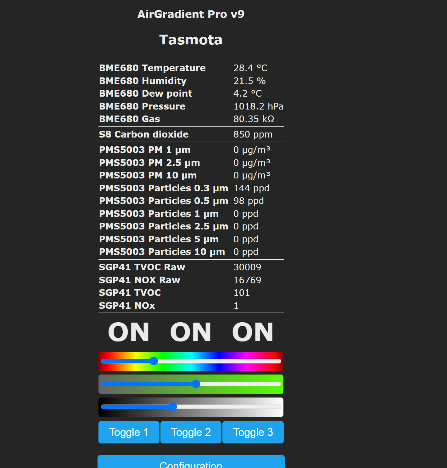
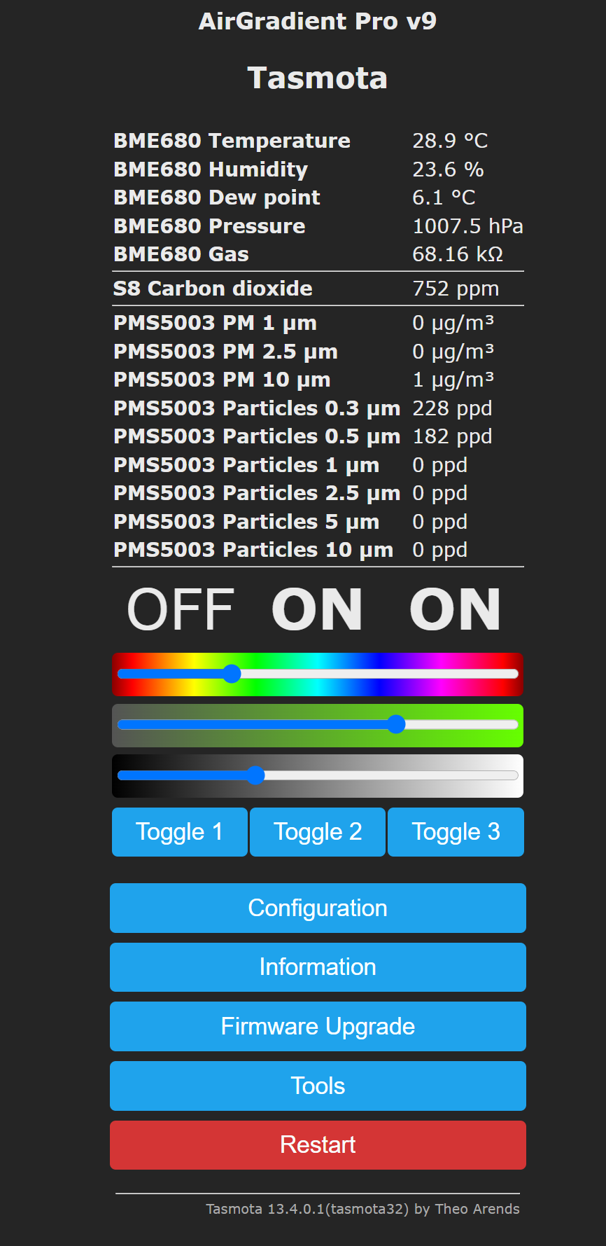
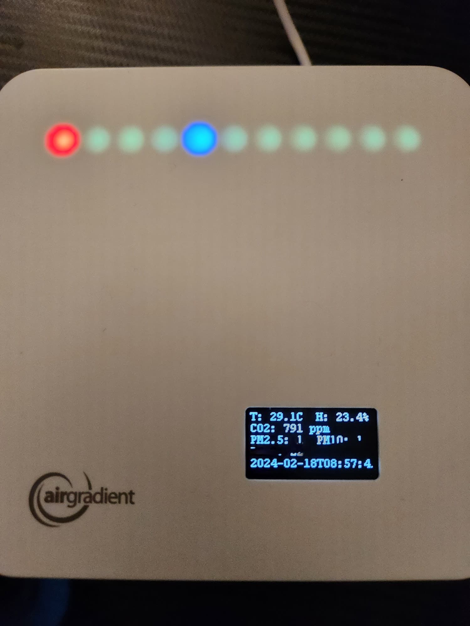
Here’s a screenshot and photo of it working:


Note:

  • Toggle1 is the watchdog relay. You probably shouldn’t click it, but it shouldn’t break anything if you do.
  • Toggle2 and the sliders is for the LEDs. It changes all the LEDs.
  • Toggle3 turns the display on and off.
  • You can set specific LEDs with the LED command. eg: led1 ff0000, led5 0000ff as shown in the photo above.

Thank you for sharing!

1 Like

No worries!

For future reference, I’ve come up with a rule that’ll change LED1 to Blue for cold, Green for good temperature, and Red for too hot. It also tracks MQTT and wifi connectivity in LED 10 and 11:

'rule1 ON Time#Minute DO Power1 On ENDON ON Time#Minute DO IF (var10=="true") Led10 00AA44 ELSE Led10 550000 ENDIF ENDON ON Time#Minute DO IF (var11=="true") Led11 00AA44 ELSE Led11 550000 ENDIF ENDON ON Mqtt#Connected DO Backlog var10 true; Led10 00AA44 ENDON ON Mqtt#Disconnected DO Backlog var10 false; Led10 550000 ENDON ON Wifi#Connected DO Backlog var11 true; Led11 00AA44 ENDON ON Wifi#Disconnected DO Backlog var11 false; Led11 550000 ENDON ON System#Init DO Backlog Dimmer2 0; Led11 550000; Led10 550000 ENDON ON SHT4X#Temperature DO IF (%value%<10) Led1 000099 ELSEIF (%value%>40) Led1 990000 ELSE Led1 009900 ENDIF ENDON'

The breakdown for easier reading and parameter modification:

Rule1
  // Turn on Power1 every minute for Watchdog.
  ON Time#Minute DO
    Power1 On
  ENDON
  
  // Change Led10 color based on var10 every minute
  ON Time#Minute DO
    IF (var10=="true") THEN
      Led10 00AA44 // Greenish color
    ELSE
      Led10 550000 // Dark red color
    ENDIF
  ENDON
  
  // Change Led11 color based on var11 every minute
  ON Time#Minute DO
    IF (var11=="true") THEN
      Led11 00AA44 // Greenish color
    ELSE
      Led11 550000 // Dark red color
    ENDIF
  ENDON
  
  // When MQTT connects, set var10 to true and Led10 to greenish color
  ON Mqtt#Connected DO
    Backlog
      var10 true;
      Led10 00AA44
  ENDON
  
  // When MQTT disconnects, set var10 to false and Led10 to dark red color
  ON Mqtt#Disconnected DO
    Backlog
      var10 false;
      Led10 550000
  ENDON
  
  // When WiFi connects, set var11 to true and Led11 to greenish color
  ON Wifi#Connected DO
    Backlog
      var11 true;
      Led11 00AA44
  ENDON
  
  // When WiFi disconnects, set var11 to false and Led11 to dark red color
  ON Wifi#Disconnected DO
    Backlog
      var11 false;
      Led11 550000
  ENDON
  
  // On system initialization, set initial states
  ON System#Init DO
    Backlog
      Dimmer2 0;
      Led11 550000; // Dark red color
      Led10 550000  // Dark red color
  ENDON
  
  // Change Led1 color based on temperature readings from SHT4X sensor
  ON SHT4X#Temperature DO
    IF (%value%<10) THEN
      Led1 000099 // Dark blue color for cold
    ELSEIF (%value%>40) THEN
      Led1 990000 // Dark red color for hot
    ELSE
      Led1 009900 // Green color for moderate
    ENDIF
  ENDON

I think that’s it for now. If others choose to use Tasmota, I hope these rules provide some good examples for LED control. I’ll see if I can get this put on the blakadder website.

I would like to put all this in a single post, but it seems I can’t edit after 24 hours.