I wonder if it’s a Power issue.
The board don’t like when there is fluctuation of power. In my case, it’s currently plugged into a USB powerhub to avoid any issue.
I wonder if it’s a Power issue.
The board don’t like when there is fluctuation of power. In my case, it’s currently plugged into a USB powerhub to avoid any issue.
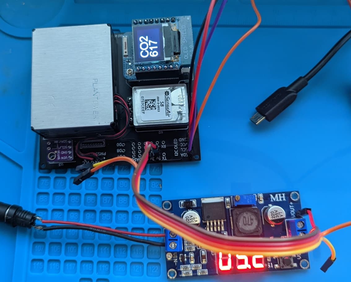
I have an adjustable buck converter I am going to try… I’ll let you know what I see with that.
I’m pretty confident that our issues with this sensor are not power, but ground plane issues.
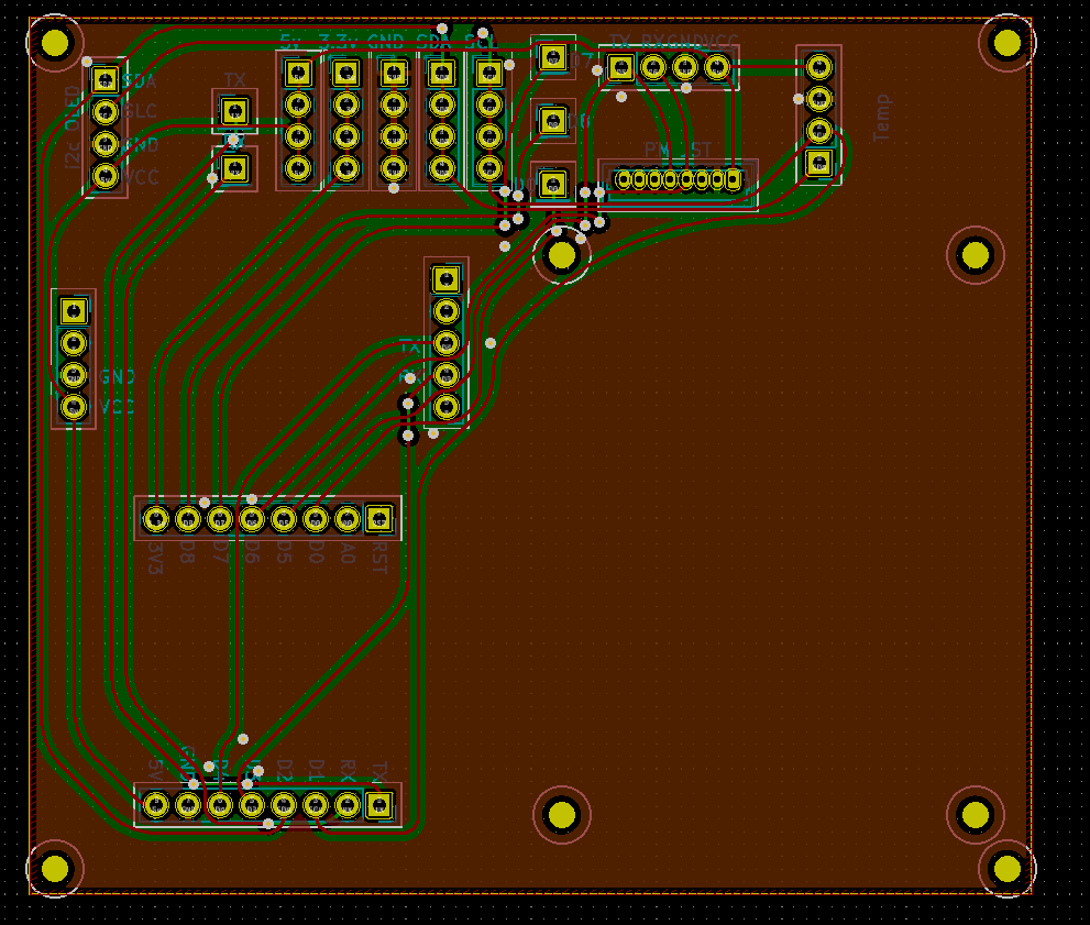
I took a look at the board on EasyEDA and it’s designed as a 2 layer board and both layers have traces going everywhere and no ground pours.
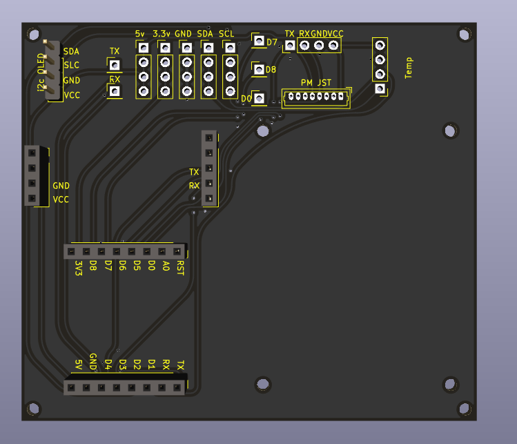
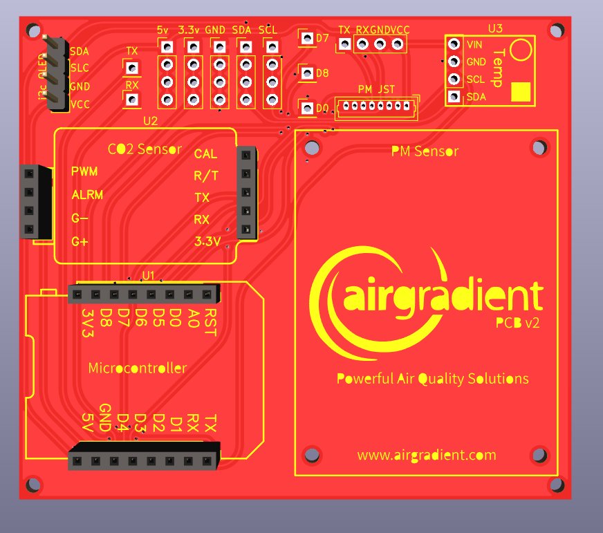
There’s nothing there to reduce EMF. I’m redesigning the board in Kicad to try to move as many traces to the front and create a solid ground pour on the back side. I just need to add the graphics and it’s good to go.
I did quite some analysis of this issue. What I see happening is a serial communication problem. Various sources in other projects are mentioning that the Softserial library has some (timing) issue. I did not have the time to try them yet but it confirms softserial as potential source for errors.
I have been running my sensor connected to my development pc for a long time. It shows the output of the 8 values of CO2Response[i] . In case of a correct reading CO2Response[0] should contain 0xFE. I observed that this value is sometimes shifted to CO2Response[1] and leads to an incorrect value. I have adopted the function AirGradient::getCO2_Raw() in airgradient.cpp and work around this problem. Maybe not the most structural solution but it works.
I am running 3 sensors since 19/02 and did not see any false reading until today.
int AirGradient::getCO2_Raw(){
	const byte CO2Command[] = {0xFE, 0X44, 0X00, 0X08, 0X02, 0X9F, 0X25};
	byte CO2Response[] = {0,0,0,0,0,0,0};
	int datapos = -1;

	while (datapos == -1) {
		_SoftSerial_CO2->write(CO2Command, 7);
		delay(100);
		int bytesinbuffer = _SoftSerial_CO2->available();

		for (int i=0; i < bytesinbuffer; i++) {
			delay(25);
			CO2Response[i] = _SoftSerial_CO2->read();
			// yield();
			if ((CO2Response[i] == 0xFE) && (datapos == -1)){
				datapos = i;
			}
			Serial.print (CO2Response[i],HEX);
			Serial.print (":");
		}
  }

  unsigned long val = CO2Response[datapos + 3]*256 + CO2Response[datapos + 4];
  Serial.println (val);
  return val;
}
I have 5 of these on the way, if anyone is interested in one, I’ll have 3 extra. PM me and I’ll send you one when they arrive.
Hey @Indymx , any success with the new board layout ?
Do you mind sharing it?
I have really weird issues on my 2nd Board CO2 sensor and I’m checking what I can improve as I want to build 3 more.
Sometimes one really does escalate
yeah, I have had 2 of them in use for 3 weeks with no issues. I very firmly believe that the issues being seen with these sensors is not a power issue at all, but a noise issue. I have run the sensor down as far as 3.73 volts with no issues at the CO2 sensor, on my revised board.
My board has almost all traces on the front. I think there are a couple very short traces on the back, but they are in a position that they don’t hurt the signal paths.
You can download the gerber files from github. I had JLCPCB make mine, I think it was about 6 bucks for 5 boards.
Does it make sense to add a capacitor to cover the temporary power drain of the co2 sensor when measuring? it seems to have overall a pretty low power consumption and then spiking to up to 1A or probably more. I changed my usb power supply for the affected airgradient and the issue seem to be gone.
But question is, is it possible to use a cap, so you are less reliant on an “high power” usb supply ?
So you can stick with older 1A than 1.2A or 1.5A just for the spikes?
Experienced the same issue with the latest Pro kit.

We tested this recently but did not find any difference with/without cap.
I have created my own version of the PCB and added the cap. I still think its super helpful because now its easily running on an 1A power supply without issues. Not related to the -1 issue tho.
Yes, that’a a good point. I will keep that in mind for a future update of the board.
We most likely found the reason for the “-1” issue. It seems to be related to the software serial.
There is a D1 mini with an ESP32. The ESP32 has several hardware serial ports and we used the same code as for the normal D1 mini (ESP8266) and just changed from software serial to hardware serial. Everything unchanged (same PCB, sensors etc) and the “-1” completely disappeared.
The next step is that we will make our Arduino library ESP32 compatible and then we might switch from the ESP8266 to an ESP32.
So does this means that this “-1” issue can’t be resolved with a D1 mini ESP8266 ?
It happens very infrequent. In our test maybe only a few times per day. There is probably a way to suppress it with the software. Long term solution would be to switch to esp32 which probably has a few other advantages.
I’m having this problem with the diy pro as well. However the co2 sensor oscillates between ~65k and -1! Before this I was getting readings but they seemed likely high still above 1k ppm co2 levels.
Are there any fixes currently?
Side question, if I pull the plug does the co2 calibration reset, or will it pick up where it left off?
Check your soldering points, sometimes it’s caused by this. >1k CO2 indoors is quite typical if you do not have a window open or fresh air through your HVAC.
The S8 will not pick up your previous readings but will do an automatic baseline calibration every 7 days.
Thanks for the quick reply, I got the pre-soldered version, how should I go about checking the soldering points? Thanks so much, for your help.
The pre-soldered version we check and test before shipment and are soldered by professionals. How long did it work? Did you do anything specific before it stopped, e.g. added a component or changes the software?